ECE 111
ECE 111. Run-Length Encoding Project (RLE). Run-Length Encoding. A simple lossless compression algorithm See http://en.wikipedia.org/wiki/Run-length_encoding Example Input: WWWWWWWWWWWW B WWWWWWWWWWWW BBB WWWWWWWWWWWWWWWWWWWWWWWW B WWWWWWWWWWWWWW

ECE 111
E N D
Presentation Transcript
ECE 111 Run-Length Encoding Project (RLE)
Run-Length Encoding • A simple lossless compression algorithm • See http://en.wikipedia.org/wiki/Run-length_encoding • Example • Input:WWWWWWWWWWWWBWWWWWWWWWWWWBBBWWWWWWWWWWWWWWWWWWWWWWWWBWWWWWWWWWWWWWW • Output:12W1B12W3B24W1B14W(Note: count is an 8-bit number. e.g., “12” is “00001100”)
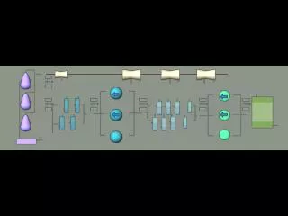
Module Interface • message_size[31:0] given in number of bytes (e.g. 67 bytes in previous example) • The size in bytes for the compressed output should be specified at output rle_size[31:0] (e.g. 14 bytes in previous example) message_addr[31:0] message_size[31:0] rle_addr[31:0] start rle_size[31:0] done port_A_clk DPSRAM (stores message) RLE Processor clk port_A_addr[15:0] port_A_we DPSRAM interface nreset port_A_data_in[31:0] port_A_data_out[31:0]
DPSRAM Interface Behavior RLE Co-Processor • To read from the DPSRAM: • Assert Port_A_addr = 0x0000, port_A_we = 0 • At next clock cycle, read data as port_A_data_out • To write to the DPSRAM: • Assert Port_A_addr = 0x0004, port_A_we = 1 • Wait for one clock cycle for write to complete • Note: you can access addresses at word boundaries only
Big-Endian vs. Little-Endian • The memory representation uses a little-endianrepresentation. • For message “ABCABCABCABC”, little-endian would be:M[0] = “ACBA”;M[1] = “BACB”;M[2] = “CBAC”;big-endian would be:M[0] = “ABCA”;M[1] = “BCAB”;M[2] = “CABC”;
Some Difficulties • Number of input or output bytes may not be a multiple of 4 (word boundary) • The compression algorithm produces variable length output • It is possible for the “compressed” output to be “longer” than the original input. • e.g., Input (12 bytes):“ABCABCABCABC” • Output (24 bytes): “1A1B1C1A1B1C1A1B1C1A1B1C”
Some Difficulties (cont’d) • If the size of the input message is not a multiple of 4, ignore the “extra bytes” • If the size of the output compressed message is not a multiple of 4, the “extra bytes” can be anything (e.g., all 0’s works)
Two Design Objectives • Minimum delay • delay = clock frequency * number of cycles • Minimum area*delay product
Test Bench • Testbench file is “rle_testbench.v” • It reads the test cases from a file called “plaintext.dat”, which contains two test cases: 1st one has 48 bytes, 2nd one has 51 bytes (be careful, only consider 3 bytes from the last memory word) • Testbench will report number of cycles for both test cases for your “delay” computation