Download
1 / 14
140 likes | 427 Vues
THE DESIGN OF POROUS PAVEMENT SHOULDERS AT RICHMOND INTERNATIONAL AIRPORT. 33 rd Annual Airports Conference March 3, 2010 – Hershey, PA Presented by: H. D. Campbell, Jr., P.E. Campbell & Paris Engineers. PROJECT DESCRIPTION. THE PROJECT

E N D
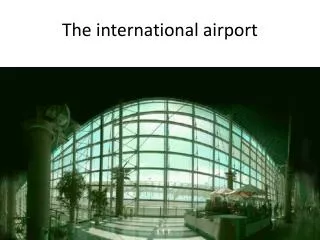
THE DESIGN OF POROUS PAVEMENT SHOULDERS AT RICHMOND INTERNATIONAL AIRPORT 33rd Annual Airports Conference March 3, 2010 – Hershey, PA Presented by: H. D. Campbell, Jr., P.E. Campbell & Paris Engineers
PROJECT DESCRIPTION • THE PROJECT • Design and construct a 35’ porous pavement shoulders at RIC along new Taxiways A & E. • Design period – 1994. • Construction period – 1995 - 1996 • THE PURPOSE • The airport is unable to provide adequate storm water retention areas for the new taxiway paved areas within present property limits. Another method of reducing the storm water time of concentration must be provided. • THE SOLUTION • Provide 35’ wide porous pavement shoulders along each edge of the new taxiways
METHODOLOGY, BACKGROUND & SITE CONDITIONS WADO requests feasibility study for justification approval Post development runoff must not exceed pre development Concerns arise over bird strike potential with existing basins Poor draining soils at the site SOIL MOISTURE AND WATER TABLE FACTORS SC and SM soils throughout site Natural moisture at 15% and above CL layer underlying area creates perched water table Site of War Between the States Battle Field DESIGN
DESIGN • STORM WATER QUANTITY AND QUALITY Intercept first 15 minutes of runoff washing over pavement Limit post development flows to pre development values Maintain quantity/quality of water in existing basins • PROVIDE FOD PROTECTION FOR GROUP 5 AIRCRAFT 35’ Shoulder Pavement Protection for Outboard Engines • STRUCTURAL DESIGN OF THE SHOULDER PAVEMENT Use 1990s AC 150/5300 for annual 2 passes of 125K dual gear landing gear configuration (250K MTOW dual gear aircraft)
DESIGN • STRUCTURAL DESIGN OF POROUS SHOULDER SURFACE • No FAA standard in 1990s • Surface Course to be P-402 3/4 to 1 inch in thickness with known performance and availability • Make up difference in surface course deficiency with stabilized base
DESIGN • STRUCTURAL/FUNCTIONAL DESIGN OF POROUS BASE/SEPARATION LAYER Porous base divided into base placed directly below the P-402 and the separation layer placed on the subgrade and below the base course Porous base #57 aggregate stabilized with cement at W/C ratio of 0.37 for structural purposes. The separation layer is #68 non stabilized aggregate Thickness of 17” based on permeability of layers Minimum permeability set for 3000 foot per day (FPD) based on cement stabilized layer Time of concentration for 17” layer at 35’ wide was 17 minutes for a 20 year storm Lateral drains placed at 300’ intervals drain to paved ditch
DESIGN • FINAL PAVEMENT DESIGN SECTION ¾-1 inch P-402 Porous Friction Course 9 inches AASHTO # 57 Cement Stabilized Aggregate (at at W/C ratio of 0.37) 7 inches AASHTO # 68 Separation Layer • PERFORMANCE In service since 1996 with no adverse reports
QUESTIONS? • Thank you for your time