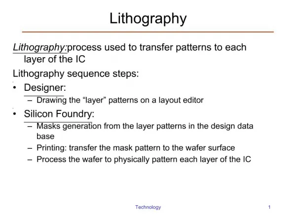
Advanced Optical Lithography
Advanced Optical Lithography. Lecture 14 G.J. Mankey gmankey@mint.ua.edu. The minimum resolution of an optical element is given by the Raleigh criterion:. The basic rule of thumb is that the minimum line width achievable is basically equal to the wave length of the incident radiation.

Advanced Optical Lithography
E N D
Presentation Transcript
Advanced Optical Lithography Lecture 14 G.J. Mankey gmankey@mint.ua.edu
The minimum resolution of an optical element is given by the Raleigh criterion: The basic rule of thumb is that the minimum line width achievable is basically equal to the wave length of the incident radiation. This limit is for classical optics, there are three "tricks" which may be applied to lower this limit: Interference lithography Phase mask lithography Near-field lithography Resolution Limit
Interference Lithography • Two coherent beams of radiation from a laser interfere to make periodic fringes with a smaller separation than the optical wavelength. • By optimizing the sensitivity of the resist, features as small as 1/10 of the optical wavelength can be obtained. ref: http://www.el.utwente.nl/smi/
Interference Lithography Setup • For large area exposures, the apparatus is complicated, since during the exposure, the system must be mechanically and optically stabilized to sub-wavelength precision. • Laser wavelengths for an Ar laser of 350 nm have been applied to produce 100 nm features such as dots and holes. • We tried this without stabilization--small vibrations completely smear out the pattern. ref: P.W. Konkola et al.
Achromatic Interference Lithography • The mirrors are replaced by gratings to selectively diffract the light to the exposure spot which relaxes the requirements on the coherence of the light source. • This technique has been applied to produce 13 nm wide posts of PMMA on Si using an excimer laser. • This system is under development by Michael Walsh, James M. Carter, Robert C. Fleming, Timothy A. Savas, Dr. Mark L. Schattenburg, and Professor Henry I. Smith at MIT.
Phase Mask Lithography • Instead of an intensity mask, light travels through a polymer mask and accumulates an additional phase relative to light that travels through the air gap. • At the corners of the phase mask in contact with the resist, light interferes destructively and there is a dip in intensity. • This can be quite sharp, possibly less than 1/4 the wavelength of the light, so 100 nm features are possible. ref. J. Aizenberg et al. Appl. Phys. Lett 71, 3733 (1997).
Photoresist Cure PDMS, remove elastomer mask from master Si Photolithography Expose through elastomer mask RIE PDMS casting Develop PDMS Phase Mask Process Ref: H. Jiang et al., Spring MRS Meeting ‘99
AFM MFM Phase Mask Needles • 200 nm permalloy needles were produced with a phase mask. A limitation discovered was the shape depended on the quality of the initial optical mask used to produce the phase mask.
Optimized Phase Mask Process • With a better mask, a periodic array of 300 nm wires was produced. • Optimizing the exposure time using the phase mask resulted in a minimum linewith of 150 nm. • After ion milling a 150 nm wide wire remained. • Contacting this wire with subsequent processing was quite a challenge.
Light illumination Membrane mask Vacuum Membrane NiCr absorber Photoresist Near Field lithography • An intensity mask with sub-wavelength gaps is placed in close proximity to the resist. • The evanescent wave emanating from the gap exposes the resist. • This evanescent wave occurs only in the near field at a distance much less than the wavelength of the light. d<<l ref: OPTICAL NEAR FIELD NANOLITHOGRAPHY.htm
Light Metal Slit Mask ~10’s nm Resist Substrate Evanescent near field region Figure 2. Evanescent near field region Limitation of Near Field Lithography • The evanescent field penetrates only a few tens of nanometers into the resist. • A two-layer resist process may be utilized to make this work. • The two-layer process is frequently used in e-beam and AFM lithography which will be discussed next. ref: OPTICAL NEAR FIELD NANOLITHOGRAPHY.htm