Download
1 / 16
160 likes | 354 Vues
Polarised Gas Targets and Polarised Ion Sources for Accelerators. Geoff Court – Physics Dept., Liverpool University. Mainly principles – time limitation Protons only – ideas apply for other nuclei (D, 3 He …..). Start point – gaseous hydrogen molecules (H 2 ). I = 0

E N D
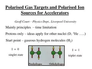
Polarised Gas Targets and Polarised Ion Sources for Accelerators Geoff Court – Physics Dept., Liverpool University Mainly principles – time limitation Protons only – ideas apply for other nuclei (D, 3He …..) Start point – gaseous hydrogen molecules (H2) I = 0 singlet state I = 1 triplet state
End point for polarised beam sources a) positive atomic ion beam with single spin state b) negative atomic ion beam with single spin state End point for gaseous polarised target c) neutral atomic beam (gas flow) with single spin state d) neutral molecular ortho beam (gas) - single spin state Applied magnetic field B - quantisation axis Polarisation P = (N - N)/ (N + N)with limits ± 1 + 1 is parallel and –1 is anti-parallel to B
Normal first stage for a), b) and c) is dissociation in a RF discharge H2 + e-g H + H + e- and other reactions. Second stage is to form an atomic beam (AB) (or use gas flow) Atoms effuse thru channel, beam formed if MFP >> diam. Thermal energy (E)– large E Large angular spread Limitation - recombination ( E = 3.4 eV) , but not in gas phase Conservation of Energy and momentum – only on surfaces
Atomic hydrogen – spin energy levels in mag field Hyperfine levels W() for F = 0 to F = 1 is 1420 MHz States 1 and 3 are QM pure spin states, 2 and 4 are mixed states
State selection type 1. Stern – Gerlach spatial separation technique Spins experience force in inhomogenous B-field F = (dBz/dz) with z axis is in direction of gradient is effective magnetic moment Hence in field B the force on the electron spin makes States 1 and 2 (mj = + ½) low field seekers (LFS) States 3 and 4 (mj = - ½)high field seekers.(HFS) Remember P << e
LFS focussed and HFS defocussed, Pe = 1 and Pn = 0.5 in low B and Pn = 0 in high B
Modify state populations with adiabatic RF transitions e.g. exchange population from 1 to 3 then Pe = 0 , Pn = -1
State selection 2. Optical pumping technique – select spin state using polarised laser source at transition frequency (LDS) Problem with H – atomic transition levels are in far UV Practical solution - pass beam through optically electron polarised alkali metal vapour (visible or IR) Spin exchange interaction gives initially – high Pe with high Pn after large number of collisions Uses Na, K, Rb or Cs
Result from 1 or 2 isa neutral atomic beam or gas flow In principle with Peor Pn = ± 1 (actually 0.8 to 0.9) Use as a gaseous target Polarised jet target Needs cool H beam Very low luminosity Storage cell target Needs cooled cell Higher lumi ( x100)
Polarised ion sources • Using an ABS or LDS - thermal atomic beam(gas flow) • a) Convert H0beam to H+ beam with an ioniser • RF discharge - electron cyclotron resonance (ECR) • High static field, electrons circulate in resonance with RF • High efficiency in small volume, field inhibits PP loss • Ion extraction, beam formation via DC potential ( 3KV) • b) Convert H0 to H • Pass H0 beam through Na vapour cell, picks up e • Works best with higher energy H0 beam
2. Using a high energy H0 beam (OPPIS) • Generate 3.5 KeV H+ beam with ECR • Capture polarised electron from optically pumped Rb atoms giving H0 (e). • Transfer electron spin to proton via Sona * transition giving H0 (p). • Ionise to H with Na cell • * Sona transition is spin state population redistribution when beam crosses a field zero
Typical OPPIS schematic layout Polarisation reversal - optical technique Change sense of circular polarisation of laser light
A High Intensity Polarised Ion Source KEK OPPIS upgraded at TRIUMF 75 - 80 % Polarization 151011 protons/pulse at source 61011 protons/pulse at end of LINAC For use in RHIC at Brookhaven
General issues • Polarisation reversal • Needs to be fast and systematic effect free • With ABS change RF transition frequency • With LDS or OPPIS change laser polarisation 2. Which technique? ABS (LDS?) for polarised targets OPPIS for polarised ion source
3. Other Nuclei • Deuteron - spin 1 Techniques mainly as for proton • 3He - spin ½, Optical pumping only as it is a two electron atom (no electron polarisation possible)
Information and references Polarised Gas Targets - Steffens and Haberli Rep. Prog. Phys. 66(2003) 1187-1935 Polarised Ion Sources for High Energy Accelerators – Levy and Zelenski Rev. Sci. Inst. 69 - 2 (1998) 732-736 International Symposium on High Energy Spin Physics - Biennial Conference series with 17th in Japan (SPIN06) this year.