Download

1 / 102
1.05k likes | 1.24k Vues
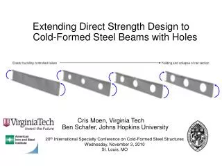
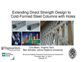
Direct Strength Design for Cold-Formed Steel Members with Perforations. Progress Report 1 C. Moen and B.W. Schafer AISI-COS Meeting February 21, 2006. Outline. Objective and challenges Project overview FE stability studies fundamentals, plates and members with holes

E N D
Direct Strength Design for Cold-Formed Steel Members with Perforations Progress Report 1 C. Moen and B.W. Schafer AISI-COS Meeting February 21, 2006
Outline • Objective and challenges • Project overview • FE stability studies • fundamentals, plates and members with holes • Modal identification and cFSM • Existing experimental column data • elastic buckling studies: hole effect, boundary conditions • strength prediction by preliminary DSMstub columns, long columns • Conclusions
Objective Development of a general design method for cold-formed steel members with perforations.
Direct strength prediction Pn = f (Py, Pcre, Pcrd, Pcrl)? • Input • Squash load, Py • Euler buckling load, Pcre • Distortional buckling load, Pcrd • Local buckling load, Pcrl • Output • Strength, Pn
Direct strength for members with holes Pn = f (Py, Pcre, Pcrd, Pcrl)? Does fstay the same? Explicitly model hole(s)? Accuracy? Efficiency? Identification? Just these modes? Gross or net, or some combination?
DSM for columns without holes 267 columns , b = 2.5, f = 0.84
Outline • Objective and challenges • Project overview • FE stability studies • fundamentals, plates and members with holes • Modal identification and cFSM • Existing experimental column data • elastic buckling studies: hole effect, boundary conditions • strength prediction by preliminary DSMstub columns, long columns • Conclusions
Project Update • Originally proposed as a three year project. Year 1 funding was provided, we are currently ½ way through year 1. • Project years 1: Benefiting from existing data 2: Identifying modes and extending data 3: Experimental validation & software
Project year 1 Focus has primarily been on compression members with isolated holes in the first 6 mos.
Outline • Objective and challenges • Project overview • FE stability studies • fundamentals, plates and members with holes • Modal identification and cFSM • Existing experimental column data • elastic buckling studies: hole effect, boundary conditions • strength prediction by preliminary DSMstub columns, long columns • Conclusions
ABAQUS Element Accuracy • Motivation • For the student to learn and understand sensitivity of elastic (eigen) stability response to FE shell element solutions • In particular, to explore FE sensitivity in members with holes • To take the first tentative steps towards providing practicing engineers real guidance when using high level FE software for elastic stability solutions of unusual situations
Stiffened element in uniform compression (benchmark: stiffened plate in compression)
Linear vs. quadratic elements S4/S4R S9R5 models compared at equal numbers of DOF
Number of elements along the length 2.5 elements per half-wave shown
S9R5 sensitivity to modeling corners 1 element in corner Use of quadratic shell elements that can have an initially curved geometry shown to be highly beneficial/accurate here. 3 elements in corner
FE vs FSM comparisons • SSMA 362S162-33 in pure compression • FE = ABAQUSFSM = CUFSM model length = half-wavelength in ABAQUS (ABAQUS boundary conditions = “pinned ends”)
Exploring local buckling difference number of local buckling half-waves in ABAQUS model (physical length of ABAQUS model is increased)
Outline • Objective and challenges • Project overview • FE stability studies • fundamentals, plates and members with holes • Modal identification and cFSM • Existing experimental column data • elastic buckling studies: hole effect, boundary conditions • strength prediction by preliminary DSMstub columns, long columns • Conclusions
Mesh sensitivity around holes 4 layers of elements shown SS SS SS SS
Mesh sensitivity around holes Do holes decrease local buckling this much??
The square plate problem • Much of the fundamental research on plates with holes has been conducted on square plates. • The idea being that one local buckle evenly fits into a square plate. • So, examining the impact of the hole in a square plate examines the impact in a localized fashion? ? =
Local buckling in an a/b = 4 plate w = 92.075mm l = 4w Conclusion? Lots of wonderful theoretical studies are not really relevant...
Local plate stability with a hole Observed loss of local stability much less than in a square plate. We will revisit this basic plot for member local buckling as well.
Outline • Objective and challenges • Project overview • FE stability studies • fundamentals,plates and members with holes • Modal identification and cFSM • Existing experimental column data • elastic buckling studies: hole effect, boundary conditions • strength prediction by preliminary DSMstub columns, long columns • Conclusions
SSMAS162-33 w/ hole Member Study L = 1220mm = 48 in.
CUFSM elastic buckling (no hole) Pcr/Py half-wavelength (mm)
ABAQUS model • Classical FSM style boundary conditions are employed, i.e., pinned free-to-warp end conditions.
Local (L) buckling • Pcrl no hole = 0.28Py, with hole = 0.28Py
Distortional (D) buckling • Pcrd no hole = 0.64Py, with hole = 0.65Py
Distortional (DH) buckling around the hole • Pcrd no hole = 0.64Py, with hole = 0.307Py
Antisymm. dist. buckling (DH2) at the hole • Pcrd no hole = 0.64Py, with hole = 0.514Py
Global flexural torsional (GFT) buckling • Pcrd no hole = 0.61Py, with hole = 0.61Py
GFT mode with hole at midspan Mixed GFT-L-D mode observed with hole near end. BC influence near the ends, under further study.. Hole location impact on GFT
SSMAS162-33 w/ hole Member Study 2 b L = 1220mm = 48 in.
Observed buckling modes L DH GFT D
“DH” mode 0.62Py 0.38Py 0.35Py 0.31Py 0.30Py
Outline • Objective and challenges • Project overview • FE stability studies • fundamentals, plates and members with holes • Modal identification and cFSM • Existing experimental column data • elastic buckling studies: hole effect, boundary conditions • strength prediction by preliminary DSMstub columns, long columns • Conclusions
Modal identification • Mixing of modes (a) complicates the engineers/analysts job (b) may point to post-buckling complications • We need an unambiguous way to identify the buckling modes • A significant future goal of this research is the extension of newly developed modal identification tools to members with holes
We can’t effectively use FEM • We “need” FEM methods to solve the type of general stability problems people want to solve today • tool of first choice • general boundary conditions • handles changes along the length, e.g., holes in the section 30 nodes in a cross-section 100 nodes along the length 5 DOF elements 15,000 DOF 15,000 buckling modes, oy! • Modal identification in FEM is a disaster
cFSM • cFSM = constrained finite strip methodThe “constraints” restrict the FSM model to deformations within a selected mode – for instance, only distortional buckling • cFSM adopts the basic definitions of buckling modes developed by GBT researchers • My research group has been developing this method as a means to provide modal decomposition and modal identification • Extension of modal identification to general purpose FE results has a potentially huge impact on our problem