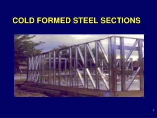
COLD FORMED STEEL SECTIONS
960 likes | 2.15k Vues
COLD FORMED STEEL SECTIONS. INTRODUCTION. extensively used in building industry manufactured by forming thin steel sheets in cold state also called Light Gauge Steel Sections or Cold Rolled Steel Sections

COLD FORMED STEEL SECTIONS
E N D
Presentation Transcript
INTRODUCTION • extensively used in building industry • manufactured by forming thin steel sheets in cold state • also called Light Gauge Steel Sections or Cold Rolled Steel Sections • number of pairs of rolls (called stages) depends on the complexity of the cross sectional shape • alternative method of forming is press – braking • galvanising provides protection against corrosion • normally, yield strength is at least 280 N/mm2
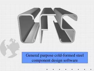
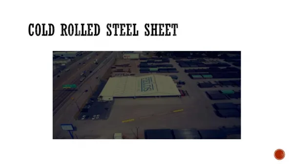
Light Gauge is a term Used In comparison to hot rolled steel to form structural shapes for framing buildings. Hot rolled steel is formed at temperatures just below melting point. Cold Formed means that the members are formed from a specific thickness and finish of sheet steel, then pressed with a form to make the shape desired. Cold rolled steel is formed at room temperature
A single sheet of paper is very weak when laid flat across two supports . . .
But may be made much stronger when folded to a different configuration . . .
Cold rolled studs and joists are formed in “C” shapes, which provides lateral strength for studs and vertical strength for joists and rafters.
Strength & Stiffness depends on Configuration, Depth, & Thickness of material Depth Thickness - Gauge
Studs are manufactured in standard sizes Standard widths are 1 ½”, 3 5/8”, 6”, and 8” Standard thickness of material is 26 gage, but thicker material is available for structural conditions. Standard Length lengths are 2’ foot increments, but custom lengths are available. Joists are made in standard depths, 6”, 8”, 10”, and 12”, and a variety of gauge thicknesses are available. Span and loading tables are provided by the manufacturers. Gage compared to thickness: 26 gage = .0179 inch thick 1/64 inch = .0156 inch thick
2’0” oc Punched for: • Wiring • Piping • Bracing
ANCHORAGE Steel studs fastened to bottom track with Self-Tapping Screws
Light Gage steel joists are similar to Light Wood Framing and just as the same for wood joists, bridging between members within spans and end blocking is required to prevent the tendency to buckle or twist under load. Reinforcing the web Of joist ends adds Strength to joists under Bearing walls
COMMON USES OF STEEL STUDS • Interior Partition Framing, either load bearing or non load bearing • Exterior Framing Heavier gage studs are required for framing of walls that Support floor and roof loads.
Brick Veneer “Mockup” showing Metal Stud Backup Wall
Channel Bracing Metal Studs as Support Structure for Exterior Gypsum Sheathing
Temporary Bracing Metal Headers EXTERIOR WALL FRAMING
Multi story building framed with exterior steel studs Applied directly to the structural frame.
Metal Studs used at the “Grill Area” in a restaurant kitchen
STEEL ROOF AND FLOOR FRAMING • Sections of steel sections to be used as joists, rafters, and trusses are similar in shape to steel studs, in that the cross section assumes a “C” shape, which is structurally oriented. • Units are made in standard sizes of 6”, 8”, 10”, and 12”. • Methods of attachment are the same as for wall framing, and assembly, bracing, and bridging is similar to techniques used in wood framing. • Structural load tables are available from manufacturer of steel joist products.
ADVANTAGES • Cross sectional shapes formed to close tolerances and can be consistently repeated for as long as required. • Any desired shape of any desired length can be produced. • Pre-galvanised or pre-coated metals have high resistance to corrosion, besides having an attractive surface finish. • All conventional jointing methods, (i.e. riveting, bolting, welding and adhesives) can be employed. • High strength to weight ratio. • light and easy to transport and erect.
Stiffened and Unstiffened Elements - stiffened element - an element which is supported by webs along both its longitudinal edges. - unstiffened element - supported along one longitudinal edge only with the other parallel edge being free to displace - intermittently stiffened element - made of a very wide thin element divided into two or more narrow sub elements by the introduction of intermediate stiffeners, formed during rolling.
Stiffened element Unstiffened element Intermediate stiffener Lips Intermittently stiffened element Edge stiffened element Stiffened and Unstiffened Elements Stiffened and Unstiffened Elements - 2
LOCAL BUCKLING • Elastic Buckling of Thin Plates A flat plate simply supported on all edges and loaded in compression will buckle at an elastic critical stress given by
Supported edge (a) Axially compressed plate simply supported on all edges Supported edge Supported edge Edge free to move (b) Axially compressed plate with one edge supported and the other edge free to move Local Buckling- 2
Edge stiffened element Unstiffened element with an edge free to move Internal element with supported edges Edges stiffened to prevent free movement Internal element Section with unstiffened element The same section with stiffened outstands Local Buckling - 3 The technique of stiffening the element
M (a) Buckled Shape M b (b) Stress Distribution Local Buckling Effects (c) Effective width Local Buckling - 4 • Post - Critical Behaviour
Local Buckling - 7 • Effective Width Concept • Lightly stressed regions at the centre are least effective. • Regions near the supports are far more effective. • The effective width, (beff) multiplied by the edge stress (e) is the same as the mean stress across the section multiplied by the total width (b) of the compression member.
Local Buckling - 13 • Maximum width to thickness ratios (IS: 801 and BS 5950, Part 5 ) • Stiffened elements with one longitudinal edge connected to a flange or web element and the other stiffened by a simple lip: 60 • Stiffened elements with both longitudinal edges connected to other stiffened elements: 500 • Unstiffened compression elements: 60
Local Buckling - 14 • Treatment of Elements with Stiffeners • Edge Stiffeners Elements having b/t60 and provided with simple lip having one fifth of the element width may be regarded as a stiffened element If b/t > 60, then the lip itself may have stability problems. Therefore “compound” lips are designed.
Intermediate stiffeners is used to transform a wide and ineffective element into highly effective element w o o Intermediate stiffener t The required minimum moment of inertia of the stiffener about the axis 0-0 Local Buckling - 15 • Intermediate stiffeners
Local Buckling - 17 • Proportioning of Stiffeners • Performance of unstiffened elements can be substantially improved by • introducing stiffeners such as lip. • introducing intermediate stiffeners. • According to BS 5950, an unstiffened element can be regarded as a stiffened element, when the lip or the edge stiffener has a moment of inertia about an axis through the plate middle surface equal to or greater than
Imin should not be less than 9.2 t4 . • For a simple lip bent at right angles to the stiffened element, the required overall depth dminis given by dmin should be less than 4.8 t Local Buckling - 18 • The Indian standard IS: 801-1975 prescribes a minimum moment of inertia for the lip given by
Beams • Laterally stable beams - Beams, which do not buckle laterally . • Designs may be carried out using simple beam theory, making modifications for local buckling of the webs. • This is done by imposing a maximum compressive stress,(which may be considered to act on the bending element ) given by
Web cleat used to avoid web crushing Space between bottom flange and supporting beam Web crushing and how to avoid it (b) Cleats to avoid web crushing (a) Web crushing Beams - 3 • Other Beam Failure Criteria • Web Crushing Generally occurs under concentrated load or at support point when deep slender webs are employed.
W Web buckling Beams - 3 • Shear Buckling • Thin webs subjected to predominant shear will buckle. • The maximum shear in a beam web is invariably limited to 0.7 times yield stress in shear. • In deep webs, where shear buckling can occur, the • average shear stress (pv) must be less than
Beams - 4 • Lateral Buckling • The great majority of cold formed beams are (by design) restrained against lateral deflections. • Lateral buckling will not occur if the beam under loading bends only about the minor axis. • Lateral buckling occurs only in "long" beams and is characterised by the beam moving laterally and twisting when a transverse load is applied
Bending and twisting Lateral Buckling Beams - 5
M M Single Curvature M M Double Curvature Single and Double Curvature Bending Beams - 7