Download
1 / 5
50 likes | 92 Vues
The effective sectional area concept was adopted to conduct the analysis of cold formed tension members. Ansys software was utilized to simulate the behavior of cold formed steel angle under tension load. Structural steel members are extensively used in structures such as bridges, roof trusses, transmission line towers, multistoried buildings etc. It gives high strength to weight ratio, resulting in the reduction of dead weight. The paper describes the case study of element types on cold formed steel angle sections under tensile using ansys. ANSYS Workbench capabilities include a unique and extensive materials and sections for concrete and steel structures. A user friendly beam and shell postprocessor included listing and plotting section geometry, reinforcements, beam stresses and strains inside the cross section. Paul Makesh A | Arivalagan S "Case Study of Element Types on Cold Formed Steel Angle Sections Under Tensile Using Ansys" Published in International Journal of Trend in Scientific Research and Development (ijtsrd), ISSN: 2456-6470, Volume-3 | Issue-1 , December 2018, URL: https://www.ijtsrd.com/papers/ijtsrd19078.pdf Paper URL: http://www.ijtsrd.com/engineering/civil-engineering/19078/case-study-of-element-types-on-cold-formed-steel-angle-sections-under-tensile-using-ansys/paul-makesh-a<br>

E N D
International Journal of Trend in International Open Access International Open Access Journal | www.ijtsrd.com International Journal of Trend in Scientific Research and Development (IJTSRD) Research and Development (IJTSRD) www.ijtsrd.com ISSN No: 2456 ISSN No: 2456 - 6470 | Volume - 3 | Issue – 1 | Nov 1 | Nov – Dec 2018 Case Study of Element Types Angle Sections Under Tensile U Angle Sections Under Tensile Using Ansys f Element Types on Cold Formed Stee n Cold Formed Steel sing Ansys Paul Makesh A1, Arivalagan S2 Paul Make 1Research Scholar Research Scholar, 2Professor and Dean M.G.R Educational And Research Institute University Research Institute University, Chennai, India Department of Civil Engineering, Dr. ABSTRACT The effective sectional area concept was adopted to conduct the analysis of cold-formed tension members. Ansys software was utilized to simulate the behavior of cold formed steel angle under tension load. Structural steel members are extensively used in structures such as bridges, roof trusses, transmission line towers, multistoried buildings etc. It gives high strength to weight ratio, resulting in the dead weight. The paper describes the case study of element types on cold formed steel angl under tensile using ansys. ANSYS Workbench capabilities include a unique and extensive materials and sections for concrete and steel structures. A user friendly beam and shell postprocessor included listing and plotting section geometry, reinforcements, beam stresses and strains inside the cross section. KEY WORDS: FEM, Mesh, Element Type, Angle sections I. INTRODUCTION CivilFEM is a set of ANSYS integrated pre processing, solution and post- processing tools that make it easier for the user to deal with civil engineering issues. The aim of the Finite Element Analysis is to develop a model that can study the behavior of single and double angle bolted cold formed steel components. The behavior during the tests was used for preparing a finite element model, particularly during the non linear analysis. In angles under tension, the highly nonlinear as the failure approaches. The model of finite elements included both geometric and nonlinear material effects. The front edge of the guesset plate is restricted in all directions except the longitudinal direction.On the front edge of the gusset longitudinal direction.On the front edge of the gusset plate, a longitudinal displacement limit condition is applied. The maximum stress and strain is obtained around the bolt hole. II. LITERATURE REVIEW Vinayak N and KalingSadanand M the connections in any structure is of importance because, it is always desirable structural member to fail first instead of the connection. If the structural connection fails before the failure of the member it is always a brittle failure and catastrophic. Present study is focused determine the structural performances beam–columns with bolted moment connections cold formed light gauge steel sections FEM analysis and experimental tests. included four types of beam column gusset plate. The number of bolts required for connection are determined 1998.Based on proposed four types of connection configuration, they are modeled in pro modeled connection is analyzed in hypermesh, then experimental test have been carried out on the same connections. The relations between moment resistance, model factor and of failure were observed. From the FEM analysis it has been observed that always torsional buckling failure of beam section distortion of gusset plate and from result model factor of proposed model is 0.731 and moment resistance of connection archives 32% to that of moment resistance of cold form steel section. Soheila Maduliat and Priyan Flange edge stiffeners can increase the ultimate moment capacity of cold-formed channel sections up to their post-yielding (inelastic) capacity. This paper yielding (inelastic) capacity. This paper The effective sectional area concept was adopted to splacement limit condition is formed tension members. applied. The maximum stress and strain is obtained Ansys software was utilized to simulate the behavior of cold formed steel angle under tension load. Structural steel members are extensively used in tructures such as bridges, roof trusses, transmission line towers, multistoried buildings etc. It gives high strength to weight ratio, resulting in the reduction of dead weight. The paper describes the case study of element types on cold formed steel angle sections under tensile using ansys. ANSYS Workbench capabilities include a unique and extensive materials and sections for concrete and steel structures. A user- friendly beam and shell postprocessor included listing LITERATURE REVIEW Vinayak N and KalingSadanand M (2015) examine connections in any structure is of primary importance because, it is always desirable the member to fail first instead of the structural connection fails before it is always a brittle failure study is focused out to structural performances of various moment connections on cold formed light gauge steel sections by analytical, FEM analysis and experimental tests. The analysis included four types of beam column connections with gusset plate. The number of bolts required for basic are determined proposed four types of connection modeled in pro-e. Further, this analyzed in hypermesh, then rcements, beam stresses and strains inside the cross section. FEM, Mesh, Element Type, Angle from from BS BS 5950 5950-5 is a set of ANSYS integrated pre- processing tools that make it easier for the user to deal with civil aim of the Finite Element Analysis is to develop a model that can study the d double angle bolted cold- carried out on the same connections. The relations between moment-rotation, moment resistance, model factor and various modes of failure were observed. From the experimental and FEM analysis it has been observed that there is s torsional buckling failure of beam section and distortion of gusset plate and from result model factor proposed model is 0.731 and moment resistance of connection archives 32% to that of moment resistance behavior observed during the tests was used for preparing a finite element model, particularly during the non linear analysis. In angles under tension, the behavior is approaches. The model of finite elements included both geometric and nonlinear material effects. The front edge of the guesset plate is restricted in all directions except the Mendis(2014) reported Flange edge stiffeners can increase the ultimate formed channel sections up @ IJTSRD | Available Online @ www.ijtsrd.com www.ijtsrd.com | Volume – 3 | Issue – 1 | Nov-Dec 2018 Dec 2018 Page: 792
International Journal of Trend in Scientific Research and Development (IJTSRD) ISSN: 2456 International Journal of Trend in Scientific Research and Development (IJTSRD) ISSN: 2456 International Journal of Trend in Scientific Research and Development (IJTSRD) ISSN: 2456-6470 investigates the post-yielding behaviour under bending of cold-formed channel sections with partially stiffened elements. The relevant literature was reviewed, experimental studies were carried out and a semi-empirical analysis was performed. Experimental and numerical analysis was undertaken of 40 cold-formed channel sections, each with a partially stiffened element. The results were compared with the existing Australian design rules and revisions are proposed to these rules. In addition, by using the test observations and the yield line mechanism model, the ultimate capacity of the tested sections was determined and compared with the test results. The model was found to provide accurate and reliable capacity predictions for slender cold-formed channel sections under bending. SonalBanchhor and M.K Gupta (2016) reported the tension members are used in a variety of structures such as trusses transmission towers etc. The most widely used structural shapes are the angle sections and the channel sections. Angle may use as single angle or double angles and the connection may be bolted or welded. Most of the design provisions for hot- rolled tension members are available and only few studies were reported in literature regarding behavior of cold formed steel bolted angle tension members. The main objective of this study is to investigate the behavior of cold steel single and double angle subjected to tension. Experimental, theoretical investigations were carried out for single angle, double angle connected to opposite sides of gusset plates and double angle connected to same of gusset plates. As a result, highly non uniform stresses will be generated near the connection, and this can cause localized yielding in parts of the cross section. The whole cross-section may not be fully utilized which causes a reduction in the net se efficiency. This loss of efficiency of the section is due to shear lag. An accurate estimation of this non uniform stress distribution determination of load carrying capacity of angles under tension. Sudha K and Sukumar S (2013) pres experimental and numerical investigation on the bending strength and behaviour of cold steel built-up flexural members. Eight specimens in two groups, first group of four specimens with equal flanges and second group of four specimens w unequal flanges have experimented. The experimental results show the experimented. The experimental results show the yielding behaviour under ed channel sections with modes of buckling and their influence on the bending strength and behaviour of CF built-up I sections. The experimental results are also verified by simulating ite element models and analysed using FEM software ANSYS. The results obtained are in good agreement with the experimental results. modes of buckling and their influence on the bending strength and behaviour of CF built experimental results are also verified by simulating finite element models and analysed using FEM software ANSYS. The results obtained are in good agreement with the experimental results. Thomas HK and Chris Ramseyer (2016) analyzed the goals of this study are to understand different buckling modes and maximum the built-up C-channels, a with evaluate 2001 Specification. For these goals, the following was conducted, different buckling modes of cold steel columns were investigated and the buckling test results of 42 cold-formed built examined. The study and review help better understanding of the buckling modes and the effect of design or testing parameters on the buckling behavior. The orientation of the column substantially impacts the maximum load of the colu 20%).The results show inconsistencies in the calculated values by AISI-2001 as compared to the maximum capacity loads determined from the buckling tests. The orientation of the member substantially impacts the maximum load of the member. Vani G and Jayabalan P ( 2013) reported the numerical analysis of cold formed steel sections using effective width method is very conservative. Hence the direct strength method has been developed recently which effectively considers the elastic buckling behavior of the member. The present study is mainly focused on the investigation of elastic buckling and the non- linear behavior of pin cold formed steel equal angles using the modern technique. A general purpose Finite Element software ABAQUS_6.11 has been used for the FE analysis and has been compared with the finite strip method. Three nominal section sizes are tested, ranging from non slender to slender sections. The specimens are studied for b/t ratio such as 30, 45 and 60.The width is varied and the thickness (2 mm) is kept constant. They are analyzed for different lengths such as 300mm, 600mm, 900mm and measurements of material properties are done by the tensile coupon test. The specimens are subjected to pressure loading to study the behavior of various sections. From the finite element analysis it is observed that the load carrying capacity of the section decreases as the b/t ratio increases. For the same b/t ratio as the length increases the load carrying capacity ratio as the length increases the load carrying capacity partially stiffened elements. The relevant literature was reviewed, experimental studies were carried out empirical analysis was performed. Experimental and numerical analysis was undertaken tions, each with a partially stiffened element. The results were compared with the existing Australian design rules and revisions are proposed to these rules. In addition, by using the test observations and the yield line mechanism model, city of the tested sections was determined and compared with the test results. The model was found to provide accurate and reliable Thomas HK and Chris Ramseyer (2016) analyzed the goals of this study are to understand different buckling modes and maximum buckling capacity of with evaluate the AISI- 2001 Specification. For these goals, the following was conducted, different buckling modes of cold-formed steel columns were investigated and the buckling test d built-up columns were examined. The study and review help better understanding of the buckling modes and the effect of design or testing parameters on the buckling behavior. The orientation of the column substantially impacts the maximum load of the column (as much as 20%).The results show inconsistencies in the formed channel SonalBanchhor and M.K Gupta (2016) reported the tension members are used in a variety of structures such as trusses transmission towers etc. The most widely used structural shapes are the angle sections and the channel sections. Angle may use as single angle or double angles and the connection may be olted or welded. Most of the design provisions for rolled tension members are available and only few studies were reported in literature regarding behavior of cold formed steel bolted angle tension members. The main objective of this study is to tigate the behavior of cold steel single and double angle subjected to tension. Experimental, theoretical investigations were carried out for single angle, double angle connected to opposite sides of gusset plates and double angle connected to same side As a result, highly non uniform stresses will be generated near the connection, and this can cause localized yielding in parts of the cross- 2001 as compared to the maximum capacity loads determined from the buckling tests. The orientation of the member substantially impacts the maximum load of the Vani G and Jayabalan P ( 2013) reported the numerical analysis of cold formed steel sections using effective width method is very conservative. Hence the direct strength method has been developed recently which effectively considers the elastic havior of the member. The present study is mainly focused on the investigation of elastic linear behavior of pin-ended cold formed steel equal angles using the modern technique. A general purpose Finite Element software s been used for the FE analysis and has been compared with the finite strip method. Three nominal section sizes are tested, ranging from non- slender to slender sections. The specimens are studied for b/t ratio such as 30, 45 and 60.The width is varied the thickness (2 mm) is kept constant. They are analyzed for different lengths such as 300mm, 600mm, 900mm and measurements of material properties are done by the tensile coupon test. The specimens are subjected to dy the behavior of various sections. From the finite element analysis it is observed that the load carrying capacity of the section decreases as the b/t ratio increases. For the same b/t section may not be fully utilized which causes a reduction in the net section efficiency. This loss of efficiency of the section is due to shear lag. An accurate estimation of this non- uniform stress distribution determination of load carrying capacity of angles is is necessary necessary for for ) presents an 1200 1200 mm. mm. Detailed Detailed experimental and numerical investigation on the bending strength and behaviour of cold-formed (CF) up flexural members. Eight specimens in two groups, first group of four specimens with equal flanges and second group of four specimens with unequal flanges have been been fabricated fabricated and and @ IJTSRD | Available Online @ www.ijtsrd.com www.ijtsrd.com | Volume – 3 | Issue – 1 | Nov-Dec 2018 Dec 2018 Page: 793
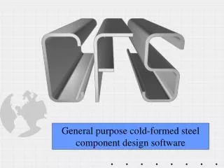
International Journal of Trend in Scientific Research and Development (IJTSRD) ISSN: 2456 International Journal of Trend in Scientific Research and Development (IJTSRD) ISSN: 2456 International Journal of Trend in Scientific Research and Development (IJTSRD) ISSN: 2456-6470 of the section decreases due to the slenderness effect. The non- linear analysis results are compared with the recent Direct Strength Method (DSM) and the traditional Effective Width Method (EWM) as well. The DSM method is found to predict the ultimate load capacities in a better way. Valdier Francisco de paula et al (2008), presented experimental results of 66 specimens carried out on cold-formed steel angles fastened with bolts under tension. Out of the 66 specimens, four angles have one bolt and remaining 62 specimens have more than one bolt per line. These 66 specimens showed net section failure with two or more bolts in the cross section of cold-formed angles. The specimens tested had equal or different legs, different cross various thicknesses and a varied number of bolts and bolt lines. He conducted multiple linear regression analysis and suggested the expression for net section efficiency (U) which depended on the geometrical factors such as connection eccentricity ( x ), connection length (L), width of connected leg of the angle (bc), net width of the angle with connected leg (bcn), width of unconnected leg (bd), nominal bolt diameter (d) and angle thickness (t).The proposed equation isU = 1.19 – 0.26 ( x /L) – (0.63b The effect of shear lag on cold-formed steel sections were much limited when ompared to studies on hot rolled steel sections. The American Iron and Steel Institute, Australian/ New Zealand and British Standard codes were incorporated the provisions. Hence there is a need to investigate the behaviour of cold-formed steel angles under tension. III. PROPERTIES OF STEEL Lightweight: Cold formed steel components weigh about 35 percent to 50 percent less than their wood counterpart, making them easy to handle during construction and transport. High-strength and stiffness: The process gives cold-formed steel one of the highest strength-to-weight ratios of any building material. This high strength and rigidity lead to more design options, wider ranges and improved material use. Fast and easy erection and installatio components made of cold-formed steel can be manufactured in a plant with high accuracy and then manufactured in a plant with high accuracy and then on decreases due to the slenderness effect. linear analysis results are compared with the recent Direct Strength Method (DSM) and the traditional Effective Width Method (EWM) as well. The DSM method is found to predict the ultimate load assembled on workstations that greatly increase erection efficiency and guarantee construction quality. assembled on workstations that greatly increase erection efficiency and guarantee construction quality. Dimensionally stable material does not expand or contract moisture content. Moreover, as time passes, it does not split or warp. It is therefore dimensionally stable. Cracked gypsum sheathed walls, nail head popping and other common problems with wood - framed structures with cold-formed steel stud walls can be virtually eliminated. IV. ELEMENT TYPE Geometry, loading and required results must all be evaluated in the selection process of the elements. The program ANSYS has a wide library of element types. Some of the features and groupings of the element types are described in this chapter to make it easier to select the element type. CONTRA 174, SOLID 186, SOILD 187, SURF 175 and TARGE types was used to model the single angle sections and double angle sections. The degrees of freedom of the element determine the discipline for which the element is applicable is structural, The element type was chosen such that the degrees of freedom are sufficient to characterize the model's response. It has both bending and membrane capabilities. The element has plasticity, elasticity, stress stiffening, creep, large deflection, and large strain capabilities, incompressible materials, and fully incompressible hyper elastic materials. Contact and sliding between 3D target surfaces was used for CONTA 174. This element applies to structural 3D and coupling field contact analy locations of the geometry and nodes are shown in Fig 1. The element is defined by eight degenerate into six nodes depending on the shape of the solid or shell elements underlying two types of geometry for this element. smoothing and bolt thread surface smoothing is a geometry correction technique that eliminates facial element in accuracies. Bold thread modeling provides a method to simulate contact between a threaded bold hole and a bolt hole without modeling th geometry of the thread. material: Cold formed steel does not expand or contract moisture content. Moreover, as time passes, it does not split or warp. It is therefore dimensionally stable. Cracked gypsum sheathed walls, nail head popping and other common framed structures in buildings formed steel stud walls can be virtually Valdier Francisco de paula et al (2008), presented experimental results of 66 specimens carried out on formed steel angles fastened with bolts under tension. Out of the 66 specimens, four angles have ns have more than one bolt per line. These 66 specimens showed net section failure with two or more bolts in the cross- formed angles. The specimens tested had equal or different legs, different cross-sections, Geometry, loading and required results must all be evaluated in the selection process of the elements. The program ANSYS has a wide library of element types. f the features and groupings of the element types are described in this chapter to make it easier to CONTRA 174, SOLID 186, and TARGE 170 are element types was used to model the single angle sections and ed number of bolts and bolt lines. He conducted multiple linear regression analysis and suggested the expression for net section efficiency (U) which depended on the geometrical factors such as connection eccentricity ( x ), connected leg of the angle (bc), net width of the angle with connected leg (bcn), width of unconnected leg (bd), nominal bolt diameter (d) and angle thickness (t).The proposed The degrees of freedom of the element determine the discipline for which the element is applicable is static element type was chosen such that the degrees of freedom are sufficient to characterize the model's response. It has both bending and membrane The element has plasticity, hyper , stress stiffening, creep, large deflection, and incompressible elasto plastic materials, and fully incompressible hyper elastic (0.63bcn + 0.17bd formed steel sections were much limited when ompared to studies on hot- rolled steel sections. The American Iron and Steel Institute, Australian/ New Zealand and British Standard codes were recently recently revised revised ere is a need to formed steel angles and and Contact and sliding between 3D target surfaces was used for CONTA 174. This element applies to structural 3D and coupling field contact analysis. The and nodes are shown in Fig The element is defined by eight nodes. it can degenerate into six nodes depending on the shape of the solid or shell elements underlying it. There are two types of geometry for this element. Surface smoothing and bolt thread surface smoothing is a geometry correction technique that eliminates facial Bold thread modeling provides a method to simulate contact between a threaded bold hole and a bolt hole without modeling the detailed PROPERTIES OF COLD COLD FORMED FORMED formed steel components weigh about 35 percent to 50 percent less than their wood handle during cold-forming formed steel one of the highest weight ratios of any building material. This high strength and rigidity lead to more design options, wider ranges and improved material use. installation: Building formed steel can be @ IJTSRD | Available Online @ www.ijtsrd.com www.ijtsrd.com | Volume – 3 | Issue – 1 | Nov-Dec 2018 Dec 2018 Page: 794
International Journal of Trend in Scientific Research and Development (IJTSRD) ISSN: 2456 International Journal of Trend in Scientific Research and Development (IJTSRD) ISSN: 2456 International Journal of Trend in Scientific Research and Development (IJTSRD) ISSN: 2456-6470 Fig 1 Element type of CONTA 174 Element type of CONTA 174 SOLID 186 is a higher order 3D 20 node solid element with a quadratic behavior of displacement. The element is defined by 20 nodes with three degrees of freedom per node in the x, y and z element supports plasticity, hyper elasticity, stress stiffening, creep, large deflection, and large strain capabilities. It also has the ability to simulate deformations of almost incompressible elasto materials and completely Incompressible materials in mixed formulation. Fig geometry, the location of the node and the element coordinate system. SOLID structural solid is suitable for irregular mesh modeling. SOLID 186 is a higher order 3D 20 node solid element with a quadratic behavior of displacement. The element is defined by 20 nodes with three degrees Fig 3 Element type of SOLID 187 Element type of SOLID 187 SURF 175decribed the geometry, node locations and the coordinate system are shown in Fig 3. elements are defined by four to eight nodes and the material properties. A triangular element may be formed by defining duplicate as described in Degenerated shape elements. The default element x- axis is parallel element. The surface tension load vector acts in the element's plane as a constant force applied to the nodes, which seeks to minimize the surface area. nodes, which seeks to minimize the surface area. directions.The elasticity, stress SURF 175decribed the geometry, node locations and te system are shown in Fig 3.The elements are defined by four to eight nodes and the A triangular element may be stiffening, creep, large deflection, and large strain It also has the ability to simulate deformations of almost incompressible elasto plastic ncompressible hyper elastic materials in mixed formulation. Fig2 shows the geometry, the location of the node and the element coordinate system. SOLID structural solid is suitable for irregular mesh K and L node numbers as described in Degenerated shape elements. The axis is parallel to the I- J side of the element. The surface tension load vector acts in the element's plane as a constant force applied to the 186 186 homogeneous homogeneous Fig 4 Element type of SURF 175 Element type of SURF 175 TARGE 170 is used to represent various 3D target surfaces for the associated contact elements. The contact elements themselves overlay the soild, shell or line elements describing the boundary of a deformable boby and are potentially in contact with the target shows the available segment types for TARGE 170.The general 3D surface segments 3 node and 6 node triangles, and 4 node and 8 node Each target segment of a rigid surface is a single element with a specific shape, or segment type. The segment types are defined by several nodes shows the element type of TARGE 170 is used to represent various 3D targ surfaces for the associated contact elements. The contact elements themselves overlay the soild, shell or line elements describing the boundary of a deformable boby and are potentially in contact w surface. Fig 4 shows the available segmen TARGE 170.The general 3D surface segments 3 node and 6 node triangles, and 4 node and 8 node quadrilaterals. Each target segment of a rigid surface is a single element with a specific shape, or segment type. The segment types are defined by sev and a target shape. Fig 5 shows the element type of TARGE 170. Fig 2 Element type of SOLID Element type of SOLID 186 The SOLID 187 element is a 3D, 10 node element in higher order. SOLID187 has a quadratic displacement behavior and is suitable for irregular mesh modelling. The element is defined by 10 nodes with three degrees of freedom per node in the x, y and z dir element has plasticity, hyper elasticity, creep, tension stiffening, high deflection and large strain capabilities. It also has the ability to simulate deformations of almost incompressible elastoplastic materials and completely incompressible hyperelastic materials in mixed formulation. The locations of the geometry nodes are shown in Fig 3 The SOLID 187 element is a 3D, 10 node element in higher order. SOLID187 has a quadratic displacement behavior and is suitable for irregular mesh modelling. The element is defined by 10 nodes with three degrees of freedom per node in the x, y and z directions.The elasticity, creep, tension stiffening, high deflection and large strain capabilities. It also has the ability to simulate deformations of almost incompressible elastoplastic materials and hyperelastic materials in Fig 5 Element type of TARGE 170 Element type of TARGE 170 mixed formulation. The locations of the geometry and @ IJTSRD | Available Online @ www.ijtsrd.com www.ijtsrd.com | Volume – 3 | Issue – 1 | Nov-Dec 2018 Dec 2018 Page: 795
International Journal of Trend in Scientific Research and Development (IJTSRD) ISSN: 2456 International Journal of Trend in Scientific Research and Development (IJTSRD) ISSN: 2456 International Journal of Trend in Scientific Research and Development (IJTSRD) ISSN: 2456-6470 V. MESH GENERATION WITH ANSYS WORKBENCH Meshing is defined as the process of dividing the whole component into a number of elements so that it distributes the load uniformly called meshing when the tensile load on the component. The meshing operation of the section involves separating the section into several smaller finite elemental fragments for efficient interaction. Therefore adopting an appropriate elements refinement and size is necessary. To analyze these angle sections by using quadratic elements and a uniform meshing arrangement with a smoother surface transition for better results. For analysis of the angle sections, the type of mesh element and the coarseness of the mesh were used. In the specimens, coarser mesh was used. Its accurate results than a more refined mesh and the coarser mesh are provide quicker analysis results tradeoff. The analysis of finite elements is a computer model of a material or design that is stressed and analyzed for specific results.Finite element analysis uses a complex system of points known as node make a mesh grid. This mesh were been designed to contain the material and structural properties that define the reaction of the structure to certain loading conditions. Depending on the anticipated stress levels of a particular area, nodes are assigned to a certain density throughout the material. The mesh acts like a spider web in that from each node, there extends a mesh element to each of the adjacent nodes. mesh element to each of the adjacent nodes. MESH GENERATION WITH ANSYS the linear elastic finite element package in the current study.During the preprocessing stage, modeling and meshing were carried out using the 3D computer ded Engineering System. The success of mesh generation depends on the right choice of the size, the linear elastic finite element package in the current study.During the preprocessing stage, modeling and meshing were carried out using the 3D computer Aided Engineering System. The success of mesh generation depends on the right choice of the size, shape and type of element. VI. CONCLUSION Geometry, loading and required results must all be evaluated in the selection process of the elements. The program ANSYS has a wide library of element types. Some of the features and groupings of the element types are described in this chapter to make it easier to select the element type. CONTRA 174, SOLID 186, SOILD 187, SURF 175 and TARGE 170 are element types was used to model the single angle sections and double angle sections. The degrees of freedom of the element determine the discipline for which the element is applicable is static structural, The element type was chosen such that the degrees of freedom are sufficie model's response. It has both bending and membrane capabilities. The element has plasticity, hyper elasticity, stress stiffening, creep, large deflection, and large strain capabilities, incompressible materials, and fully incompressible hyper elastic materials. REFERANCES 1.ANSYS Release 8.1 (2004). ANSYS, Inc., USA. Google Scholar 2.AS/NZS (1996). Australian/New Standard, Cold- Formed Steel Structures, Sydney, Australia. Google Scholar 3.Desmond, T. P., Pekoz, T., and “Edge stiffeners for thin Journal of Structural Engineering, 107(2), pp. 329–353.Google Scholar 4.Lam, S. S. E., Chung, K. F., and Wang, X. P. (2006). “Loadcarrying capacities of cold steel cut stub columns with lipped C Thin-Walled Structures, 1083.Google Scholar 5.NAS (2001). Specification for the Design of Cold formed Steel Structural American Specification, Washington, D. Google Scholar Meshing is defined as the process of dividing the whole component into a number of elements so that it distributes the load uniformly called meshing when the tensile load on the component. The meshing operation of the section involves separating the n into several smaller finite elemental fragments Therefore adopting an Geometry, loading and required results must all be evaluated in the selection process of the elements. The S has a wide library of element types. Some of the features and groupings of the element types are described in this chapter to make it easier to CONTRA 174, SOLID 186, and TARGE 170 are element o model the single angle sections and appropriate elements refinement and size is necessary. To analyze these angle sections by using quadratic elements and a uniform meshing arrangement with a moother surface transition for better results. For analysis of the angle sections, the type of mesh element and the coarseness of the mesh were used. In the specimens, coarser mesh was used. Its shows a more refined mesh and the analysis results as a The degrees of freedom of the element determine the discipline for which the element is applicable is static structural, The element type was chosen such that the degrees of freedom are sufficient to characterize the model's response. It has both bending and membrane capabilities. The element has plasticity, hyper elasticity, stress stiffening, creep, large deflection, and incompressible elastoplastic ully incompressible hyper elastic tradeoff. The analysis of finite elements is a computer model of a material or design that is stressed and analyzed for specific results.Finite element analysis uses a complex system of points known as nodes that mesh were been designed to contain the material and structural properties that define the reaction of the structure to certain loading conditions. Depending on the anticipated stress levels gned to a certain mesh acts like a spider web in that from each node, there extends a ANSYS Release 8.1 (2004). ANSYS, Inc., USA. AS/NZS (1996). Australian/New Formed Steel Structures, Sydney, Zealand Zealand Pekoz, T., and winter, G. (1981). “Edge stiffeners for thin-walled members.” Journal of Structural Engineering, 107(2), pp. Fig 6 Tetrahedron mesh Tetrahedron mesh Lam, S. S. E., Chung, K. F., and Wang, X. P. (2006). “Loadcarrying capacities of cold-formed ub columns with lipped C-section.” Walled Structures, 44, 44, pp. pp. 1077 1077– Fig 7 Hexahedral mesh shows the Tetrahedron mesh and the Hexahedral mesh each of the angle specimens was analyzed using NAS (2001). Specification for the Design of Cold- formed Steel Structural American Specification, Washington, D. C. Members, Members, North North Fig 7 shows the Tetrahedron mesh and the Hexahedral mesh each of the angle specimens was analyzed using @ IJTSRD | Available Online @ www.ijtsrd.com www.ijtsrd.com | Volume – 3 | Issue – 1 | Nov-Dec 2018 Dec 2018 Page: 796