Download
1 / 22
230 likes | 409 Vues
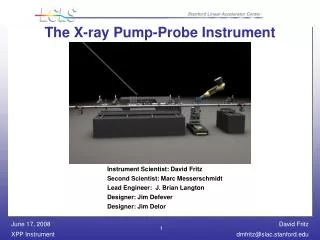
The X-ray Pump-Probe Instrument. Instrument Scientist: David Fritz Second Scientist: Marc Messerschmidt Lead Engineer: J. Brian Langton Designer: Jim Defever Designer: Jim Delor. Outline. Brief Instrument Overview Sample Goniometer System Detector Mover System Optics Table Design

E N D
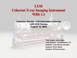
The X-ray Pump-Probe Instrument Instrument Scientist: David Fritz Second Scientist: Marc Messerschmidt Lead Engineer: J. Brian Langton Designer: Jim Defever Designer: Jim Delor
Outline • Brief Instrument Overview • Sample Goniometer System • Detector Mover System • Optics Table Design • Conclusion
XPP Experimental Techniques • Time-Resolved X-ray Diffraction (TRXD) • Time-Resolve Diffuse Scattering (TRDS) • Time-Resolved Protein Crystallography (TRPX) • X-ray Emission Spectroscopy (XES) • Small Angle X-ray Scattering (SAXS) • Optical Probing of X-ray Transients * The instrument budget is not sufficient to provide capability to all techniques
XPP Instrumentation Categories • X-ray Beam • Preparation (spatial profile, intensity, spectrum, repetition rate) • Delivery to sample • Characterization (spatial profile, intensity, arrival time) • Optical Beam • Creation • Preparation (spatial profile, intensity, spectrum, repetition rate, temporal profile) • Delivery to sample • Characterization (spatial profile, intensity, spectrum, temporal profile) • Sample Environment • Orientation & Positioning • X-ray Detection
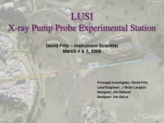
XPP Instrument Location Near Experimental Hall X-ray Transport Tunnel AMO (LCLS) XPP Endstation XCS CXI Far Experimental Hall
Detector Mover – Design Goals • Flexibility to accommodate a wide variety of sample environments • Capable of orienting small samples (~ 50 μm) over a wide range of reciprocal space • Sphere of confusion < 30μm • Open access to allow close proximity laser optics • No interference with direct beamline while in monochromatic mode
Sample Goniometer – Tilt Platform • 400 mm x 400 mm top surface • ± 5°angular range of arc segments • Large load capacity (>> 50 kg) • 200 mm working distance
Detector Mover – Design Goals • Operate in both interaction points • 10 cm – 100 cm sample to detector distance in forward-scattering upper hemisphere quadrant • 10 cm – 50 cm sample to detector distance in back-scattering upper hemisphere quadrant • Repeatable position the XPP detector pixels to a fraction of the pixel size • Definitively know the position of all detector pixels to a fraction of the pixel size
Detector Mover – Concept • 6-axis Industrial Robot • Load capacity (> 20 kg) • ± 50 µm repeatability • Floor or ceiling mountable • No counterweights • Remotely variable sample to detector distance • Remote control of detector clocking angle
Detector Mover – Path Forward • Engineering and manufacturing will be broken up into 3 work packages • Statement of work 1 • Verify that a industrial robot has the capability of meeting motion requirements • Statement of work 2 • Create a concept for integrating robot into the XPP instrument • Statement of work 3 • Manufacturer, install, test and integrate system
Detector Mover – SOW 1 Test 1 • Test 1 – Spherical motion and pointing • System is capable of moving the detector about a spherical surface of a user defined radii while pointing the detector at the interaction region • Test 2 – Repeatability • Measure repeatability and hysterisis of system • Test 3 – Detector Clocking Angle • Measure how well the clocking angle can be controlled • Test 4 – Stability • Measure long term (~ hours) motion drift for various fixed positions Test 2
Detector Mover – SOW 2 • Concept for integrating system into XPP • Robot arm mounting • Reach requirements can be met without intruding into mechanical stay clear zones • Safety system
Optics Support Table – Design Goals • Repeatable position optics in two operating positions (mono, direct) • Initial beam based alignment is expected for each position but the desire is to have a configuration file loaded for each operating mode without the need for alignment • Stably support X-ray optics and diagnostics • Design logic: • Optical axis will be defined by XPP slits • X-ray optics and interaction point can drift together on the order of 100 µm with minimal impact • However, the diffractometer thermal drift is an unknown • It was determined that it was best to design a support table that fixes the position and alignment of the optical elements to the highest extent reasonably achievable • This reduces misalignment issues to a one dimensional problem • Design goals in priority order: • Stability of optics with respect to each other over short and long term periods • Absolute position stability • Slits are the gold standard and need to be the most stable of all elements
Optics Support Table – Case Studies • Analyzed component displacement due to bowing of support structure for a 2° F temp change • Analyzed global displacement of entire structure due to 2° F thermal expansion • Large granite surface plate with a low profile strongback was best option • Themalization time constant of the granite is many days • However, the drawback is the rigging effort – must be moved in through the FEH
Optics Support Table – Design • Strongback has been split into two sections to minimize bowing and to prevent system overconstraints • Strongback is strategically tied down to rails near locations of slits
Questions for the Committee • Is the sample goniometer design optimized form the scientific goals of the instrument? • Are the sample mover design requirements reasonable? • Does the sample mover path forward seem reasonable? • Is the design logic of the optics support table valid? • Any other concerns/comments?