Aircraft Familiarization
Authored by Rich Simerson 01-Jun-2007 Updated 01-Apr-2010 (2) Modified by Lt Colonel Fred Blundell TX-129 Fort Worth Senior Squadron For Local Training Rev 5.0 02-Jan-2014.

Aircraft Familiarization
E N D
Presentation Transcript
Authored by Rich Simerson 01-Jun-2007Updated 01-Apr-2010 (2)Modified by Lt Colonel Fred BlundellTX-129 Fort Worth Senior Squadron For Local Training Rev 5.0 02-Jan-2014
This Training Slide Show is a project undertaken by Lt Colonel Fred Blundell of the TX-129 Fort Worth Senior Squadron, Fort Worth, TX for local use to assist those CAP Members interested in advancing their skills. The information contained herein is for CAP Member’s personal use and is not intended to replace or be a substitute for any of the CAP National Training Programs. Users should review the presentation’s Revision Number at the end of each file name to ensure that they have the most current publication.
AircraftFamiliarization Why do I need to know this stuff anyway? Structure Instrumentation Weight & Balance Pre-flight inspection Safety Ground operations Wake turbulence Flightline signals
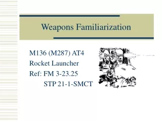
The Airplane CAP typically uses C172 and C182
The RudderControls Yaw Directional Control of the Aircraft on the ground is by the rudder peddles and linkages to the nose gear.
TypicalInstrument Panel DO NOT reposition any aircraft instrument's settings or controls without first asking the pilot.
Magnetic Compass Primary Doesn’t require any power Used to set HI (DG) Installation problems Bank angles and speed changes can cause a compass to show the wrong heading
Heading Indicator Vacuum gyro (Directional gyro) Stable indications Quick response to turns Electrical or vacuum-driven Will drift, requires periodic re-alignment
Altimeter Static pressure Usually set to show pressure altitude above Mean Sea Level (MSL) Accurate altitude is dependent on the altimeter setting.
Turn Coordinator Electric Really two instruments Miniature aircraft shows turn rate only - does not show bank angle Inclinometer shows quality of turn - Coordinated, slip, skid
Attitude Indicator Vacuum gyro Highly reliable & useful Provides a horizon reference Hash marks indicate bank angle Climb/descent marks
Static & Ram pressure Knots (and/or MPH) Colored markings show ranges Shows aircraft speed through the air Airspeed Indicator
Vertical SpeedIndicator Static pressure rate of change Climb or descent rate Has a lag due to design Use with altimeter
Tachometer RPM Markings — green arc Indicates power
Other Instruments Gauges Fuel (accurate at empty) Manifold pressure Fuel flow Oil Temperature and Pressure Vacuum and Generator Exhaust Gas Temperature Instruments vary from aircraft to aircraft
Nav/Comm Primary and Standby Frequencies (flip-flop) Navigation Communications
Comm Antennas Normally mounted on top One for each radio Know for your aircraft, if they are on top or on the bottom
Nav Antennas “Cat whisker” style One for each nav May be dual blade (Bonanza)
Static “Wicks” Mitigate buildup of static electricity (interferes with comm) Wings, elevators, vertical stabilizer Take care when walking around
Other Antennas Loop (Directional) ADF Marker Beacon
GPS Apollo GX55 ARNAV Star 5000
GPS Antenna Line of sight, so mounted at the very top Comm antennas can interfere with the weak signals, so they are tested for interference GPS
UHF Antenna Blade type (may be spike) Transponder & DME [If mounted up front, may interfere with DF]
Navigation Instruments VHF Omnidirectional Range (VOR-DME, VORTAC) Indicates direction to/from ground transmitter relative to magnetic North Automatic Direction Finder (NDB) Direction toward ground transmitter relative to airplane nose VOR ADF
Weight and Balance The wings generate a limited amount of lift Maximum weight for an aircraft is set by the manufacturer Pitch stability is affected by the location of the center of gravity The pilot computes weight and balance and controls it by loading the aircraft correctly
Weight and Balance Excessive weight adversely impacts performance: Longer take off and landing distance Reduced climb performance Reduced ability to withstand turbulence and wind shear forces Out of Forward C.G. limits can cause: Reduced up-elevator authority (ability to raise the nose) Can eliminate the ability to flare for landing Out of Rear C.G. limits can cause: Reduced down-elevator authority (ability to lower the nose) Can make stall recovery difficult or impossible
Aircraft Pre-flight WALK AROUND WINGS FUSELAGE PROPELLER CONTROLS LIGHTS TIRES OIL FUEL COWLING TIE DOWNS CHOCKS
Safety — Three Rules NEVER sacrifice safety to save time Use established procedures and checklists You may have to deviate from common procedures — if you do, use common sense and prudent judgment (see Rule #1) The most dangerous part of a mission is driving to and from the airport or mission base!
SafetyIn/Around Aircraft No smoking Keep clear Fire on the ground Moving and loading the aircraft Entry/Egress - normal and emergency Seat belts and shoulder harnesses (<1,000’) Fuel management – you have an interest in making sure you don’t run out of fuel. The pilot should brief the crew on how much fuel will be needed and where you’ll refuel, if necessary.
At Emergency Egress
AircraftRefueling Procedures FUEL CAPS GROUND WIRE CHOCKS FUEL SUMP DRAINS
Safety During Taxiing Taxiing – All crewmembers looking for obstacles Obstacle within six feet – get out and push Obstacle within 6 to 10 feet – get a marshaller or “wing walker” No unnecessary talk (sterile cockpit) Obey flightline hand signals But use common sense – many linemen are inexperienced
FlightlineHand Signals Hands out making a pulling motion COME AHEAD Outward motion with thumbs PULL CHOCKS Inward motion with thumbs INSERT CHOCKS Circle with hand START ENGINE
FlightlineHand Signals Motion forward, pointing left TURN LEFT Motion forward, pointing right TURN RIGHT Thumb up ALL CLEAR - O.K. Downward motion with palms SLOW DOWN
FlightlineHand Signals Crossing hands over head EMERGENCY STOP Hands crossed above head STOP Slash throat with finger CUT ENGINE
AgainSafety During Taxiing Taxiing – All crewmembers assist the pilot Prevent collisions with other aircraft and vehicles Help the pilot find and stay on the taxiway (bad weather, low visibility, night on an unlighted airport) Be familiar with airport signs and markings Runway markings are white and taxiway markings are yellow
Airport Signs and Markings Follow the yellow lines Stay behind the dashed lines Need ATC permission to cross the solid lines
Airport Signs and Markings (Continued) Mandatory signs have a red background with a white inscription May have a row of red stop bar lights embedded in the pavement. When illuminated, do not cross (even if given permission by ATC) Location boundary signs have a yellow background with a black inscription Visible from the runway Visual clues to determine when you’re clear of the runway
Airport Signs and Markings (Continued) Location signs have a black background with a yellow inscription Direction signs have a yellow background with a black inscription
Airport Related ATC Clearances • Be familiar with ATC ground clearances that involve the airport signs and markings • Back up the pilot when taxiing • Controllers are required to get acknowledgement of all “hold short” instructions • Pilot/Observer should read back all clearances • “Cleared to taxi” or “Taxi” (implied clearance) • “Cleared for takeoff runway 22”
Airport Related ATC Clearances (Continued) • Meaning of clearances: • “Taxi to …” Cleared to taxi to any point other than assigned takeoff runway. Cleared to cross all runways that intersect the taxi route. Does not authorize taxiing onto or crossing assigned runway. • “Taxi to … hold short of …” Cleared to taxi, but enroute to taxi clearance limit must hold short of another taxiway or crossing runway.
Airport Related ATC Clearances (Continued) • Meaning of clearances: • “Cross runway …” Cleared to cross the runway crossing your taxi route and continue to taxi clearance limit. • “Hold short …”Do notenter or cross the taxiway or runway specified by the controller. If there is a painted hold line, do notcross it. • “Report position” Identify your location on the airport.