Download

1 / 30
340 likes | 533 Vues
Learn about SISO, SIMO, MISO, and MIMO radar ambiguity functions, Doppler and range resolution, multiple targets, LFM, and MIMO radar advantages.

E N D
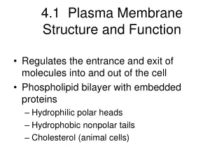
Understanding of SISO, SIMO, MISO and MIMO (note that the terms input and output refer to the radio channel carrying the signal, not to the devices having antennas)
Radar Ambiguity Function t: delay n: Doppler u(t-t)ej2pnt u(t)
Radar Ambiguity Function t: delay n: Doppler u(t-t)ej2pnt u(t) Matched filter output
Radar Ambiguity Function t: delay n: Doppler u(t-t)ej2pnt u(t) Matched filter output
Radar Ambiguity Function t: delay n: Doppler u(t-t)ej2pnt u(t) Matched filter output Radar ambiguity function
Radar Ambiguity Function • Ambiguity function characterizes the Doppler and range resolution. t: delay n: Doppler u(t-t)ej2pnt u(t) Matched filter output Radar ambiguity function
Radar Ambiguity Function Multiple targets (tk,nk)
Radar Ambiguity Function Multiple targets (tk,nk)
Radar Ambiguity Function Multiple targets (tk,nk) Matched filter output
Radar Ambiguity Function Multiple targets (tk,nk) Matched filter output n target 1 (t1,n1) target 2 (t2,n2) t
Radar Ambiguity Function Multiple targets (tk,nk) Matched filter output n target 1 (t1,n1) target 2 (t2,n2) t
Radar Ambiguity Function • Ambiguity function characterizes the Doppler and range resolution. n target 1 (t1,n1) target 2 (t2,n2) t Ambiguity function
Radar Ambiguity Function • Ambiguity function characterizes the Doppler and range resolution. n target 1 (t1,n1) target 2 (t2,n2) t Ambiguity function
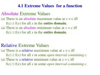
Properties of Radar Ambiguity Function • Signal component n t
Properties of Radar Ambiguity Function • Signal component • Energy n t
Properties of Radar Ambiguity Function • Signal component • Energy • Symmetry n t
Properties of Radar Ambiguity Function • Signal component • Energy • Symmetry • Linear frequency modulation (LFM) n t
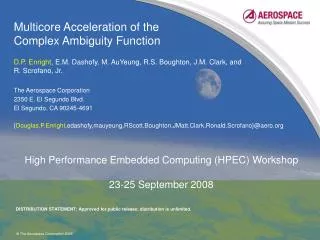
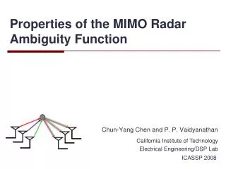
The radar systems which emits orthogonal (or noncoherent) waveforms in each transmitting antennas are called MIMO radar. MIMO Radar MIMO radar SIMO radar (Traditional) w2f(t) f2(t) w1f(t) f1(t) w0f(t) f0(t) • Advantages • Better spatial resolution • Flexible transmit beampattern design • Improved parameter identifiability
Properties of the signal component • Ambiguity function: • Signal component:
Linear frequency modulation (LFM) • Linear frequency modulation
Linear frequency modulation (LFM) • Linear frequency modulation • Cross ambiguity function
Linear frequency modulation (LFM) LFM Shear off n t n t
Linear frequency modulation (LFM) LFM Shear off n t n t The range resolution is improved by LFM. n n t t
Radar Ambiguity Diagram The thumbtack ambiguity function is common to noiselike or pseudonoise waveforms. By increasing the bandwidth or pulse duration the width of the spike narrow along the time or the frequency axis, respectively. Where: B - bandwidth T - pulse width fd - doppler delay td - time delay This shows that as we increase the bandwidth B, we have better range resolution. Conversely if we increase the pulse width T, we increase the doppler resolution.
Radar Ambiguity Diagram Doppler Delay The first null occurs at The main peak of the ambiguity function corresponds to the resolution of the system in terms of range and Doppler. The additional peaks correspond to potential ambiguities, resulting in confusion at choosing the correct range of the target and its velocity
Analog FM Ambiguity Diagram • Analog FM – Speech Ambiguity Plot
Digital Audio Ambiguity Diagram • Ambiguity Plot with speech content