Download

1 / 24
240 likes | 339 Vues
Explore PCB design techniques and routing methods for handling high-speed 1 Gbps signals in ECE 4006. Learn to differentiate signal types and apply appropriate treatments based on frequency and sensitivity, including transmission line issues and signal return path considerations.

E N D
PCB Design for 1 Gbps ECE 4006 Dr Brooke
Overview • What signals are being routed? • How can you route those signals? • How to apply routing to PCB? • PCB design techniques
Signals being routed • High Frequency Sensitive Analog (e.g., IN from PD) • High Frequency: Data, and Noisy Analog (e.g., +OUT from Limiting Amp, +OUT from VCSEL driver) • Low Frequency sensitive : Bias, Analog (e.g., DC Power on input side of most chips esp. TIA) • Low Frequency insensitive: Bias, Analog (e.g., DC Power on output side of most chips, low frequency data)
Signal Type Matrix • Red = Challenging, Yellow =Care needed, Green = Easy
Different Types NeedDifferent Treatment • High Frequency/High Sensitivity • Transmission lines, return path (decoupling), Shielding from high frequency • High Frequency/Low Sensitivity • Transmission lines, prevent coupling to sensitive • Low Frequency/High Sensitivity • Shielding from high frequency, return path (ground loops), • Low Frequency/Low Sensitivity • Low Frequency decoupling, Resistive Loss
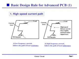
High Frequency/High Sensitivity • Transmission line issues • Signal return path issues (decoupling) • Shielding from larger high Frequency signals
Transmission line issues • What is a Transmission line? What is not? • How to avoid (short lines) • How to use (50 ohms) • Non traditional transmission lines (turns, tapers)
What is a Transmission line 1 wavelength = = 20 cm @ 500 MHz, • Less that 1/10 of a wavelength use arbitrary geometry connections • More that ¼ wave length use wideband RF design techniques for geometry (stripline, coplanar) • In between use special angles, tapers, curves EM wave ¼ wavelength or greater = transmission line = 5 cm 1/10 wavelength or less = wire = 2 cm
What is a Transmission line • What frequency to use? • Gbps data ~ 500 MHz sq wave (10101010…) Square Wave = 1st + 3rd + 5th … Harmonics Using up to 5th harmonic has eye closure ~15% Using up to 3rd harmonic has eye closure ~30% Using only 1st harmonic has eye closure ~50%
How to avoid Transmission lines? • Depending on eye you want chose appropriate harmonic length to be less than a 1/10th of a wavelength First Harmonic = 1/10 * 20 cm = 2 cm Second harmonic (present in real data) = 2 cm / 2 = 1 cm Fifth Harmonic = 4 mm Third Harmonic = 6.7 mm Fourth Harmonic = 5 mm
How to avoid Transmission lines? For Gigabit Ethernet • Nice eye for lines less than 4 mm not a transmission line • OK eye for lines less than 7 mm not a transmission line • Poor eye for lines less than 2 cm not a transmission line
How to use Transmission Lines • Terminate them in design impedance • Ensure high frequency return path • Signal returns along the shield of Coax 50 ohms Signal arrives after transmission delay. “sees” 50 ohms immediately between core and shield - nothing else if terminated properly - “echo” after 2 x transmission delay otherwise
+ +OUT 100 ohms GND -OUT + “sees” 50 ohms immediately between core and shield How to use Transmission Lines • Special Case for Balanced Differential Signals • Connect shields together “sees” 50 ohms immediately between core and shield Balanced = equal and opposite That is for AC components: (+OUT) = -(-OUT)
How to use Transmission Lines • Eliminate reflective features larger than 1/10th of a wavelength • Avoid impendence changes 45 deg 45 deg 1/10th wavelength 1/10th wavelength
Non traditional transmission lines (curves, tapers) • If you want to use these features either: • Do it in the transition region between 1/10th and ¼ wavelength • Or use an RF design tool (e.g., ADS) to verify operation with finite element analysis
Signal return path issues (decoupling) • Every High Frequency input and output • All AC current out/in must return to both “nearby” supplies VCC OUT Load VEE “Decoupling Capacitor” – Must be a “short” at signal frequency ground path – minimum length!
Decoupling Capacitors • www.murata.com/cap/lineup • We are using 1.6 mm x 0.8 mm (0603) caps
Decoupling caps • 10000 pF = 0.01 uF • S11 = reflected/incident power ratio when grounded • S21 = ratio of power passed to 50 ohm load
High Frequency/Low Sensitivity • Transmission line issues • prevent coupling to sensitive
Low Frequency/High Sensitivity • Shielding from high frequency • Return path (ground loops)
Low Frequency/Low Sensitivity • Low Frequency decoupling • Resistive Loss
PCB design techniques • fff