Download
1 / 52
540 likes | 758 Vues
P13623: Conductive Heat Transfer Lab Equipment. System Design Review April 5th, 2013. Project Participants. Project Sponsor : RIT KGCOE, Chemical Engineering Dept. Dr. Karuna S. Koppula Mr . Paul Gregorius MSD 1 Team Guide: Michael Antoniades Project Members:

E N D
P13623: Conductive Heat Transfer Lab Equipment System Design Review April 5th, 2013
Project Participants Project Sponsor : RIT KGCOE, Chemical Engineering Dept. Dr. Karuna S. Koppula Mr. Paul Gregorius MSD 1 Team Guide: Michael Antoniades Project Members: • David Olney - (ChemE) Project Manager • Todd Jackson - (ME) Project Engineer • AlyshaHelenic - (ChemE) Documentation Engineer • Edward Turfitt - (ChemE) Design/Concept Engineer • Charles Pueschel - (ChemE) Data Acquisition Specialist • Ian Abramson - (ChemE) Customer Liaison
Agenda • Overview of project • Design specifications, needs and constraints • Customer needs • Engineering specifications • Project deliverables • Functional decomposition • Design process • Concept generation • Functional architecture • Physical architecture • Design generation and assessment • Initial concepts • Pros and cons • Final proposed design • Final design assessment • Benefits and limitations • Feasibility • Risk • Project planning • Project schedule • Deliverables • Quarter goals • Questions
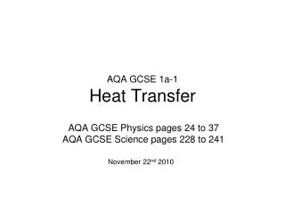
Heat Transfer and Thermal Conductivity • Heat transfer can take place from three methods (Conduction, Convection , Radiation). • The most valuable method to calculate a constants for one specific mode of heat transfer is to reduce or eliminate the other two modes.
Project Overview Problem Statement: • Build an apparatus that can demonstrate thermal conductivity reliably to students for educational purposes. Resources: • The only limitation we have is the set budget for the project. • (space, cart, current lab equipment, donations) excluded from budget. Expectations: • The purpose of this review session is for constructive criticism, recommendations, and validation by the customer for some of our current designs that we have derived.
Design Process Flow PRP Functional Decomposition Problem Definition Engineering Matrix House of Quality Constraint Criteria Define Constraints Define Requirements Power Source Temperature Sensors Heating Element Cooling Element Insulation Methods Data Collection Contact Resistance Interchangeability Define Systems Research Systems Develop Solutions Concept Generation External Assess Solutions Pugh Matrix Design 4 Design 2 Design 3 Design 1 Generate Designs Pro/Con List Assess Designs Final Design Final Design Design assessment Customer Specifications review Risk Assessment Cost Assessment
Functional Architecture Heating Element Provide a constant heat source to the specimen Cooling Element Provide a constant heat sink to the specimen Temperature Sensors Provide a means for measuring temperature Insulation Minimize the amount of heat loss Data Acquisition Provide a means for collecting data Power Source Provide a means for power heating element
Pros & Cons of Design 1 Pros Simplicity Cheap Visual Compatible with different samples Easy to set up Cons Inconsistent insulation
Pros & Cons of Design 2 Pros Pressure can be applied to the heater Cheap Visual Compatible with different length samples Cons Hard to swap different diameter samples Potential air leaks because of water supply connections.
Pros & Cons of Design 3 Pros No convection Compatible with different length Pressure can be applied on both the heater and cooler Solid insulation adds support Cons Complex Longer set up times Not completely visible
Pros & Cons of Design 4 Pros Limits convections Visual Compatible with different length and diameter samples Pressure can be applied on both the heater and cooler Compatible with multiple insulations Cons Complex Longer set up times More expensive
Boat Design Removable caps allow liquid , gases, and pastes to be inserted into the boat. Temperature sensors will be placed at set lengths within the boat so that they do not move. The ends will be made out of a conductive medal to minimize leakage.
Physical Architecture System Heat conduction apparatus Subsystem Power source Temperature sensor Heating element Cooling element Insulation Data Collection Contact resistance Multi-material Plate heater Screw cap (pressure) Variable insulation method Components Cold plate DAQ Boats Electric variable power generator Thermocouple or silicon based temperature sensor LCD
Temperature In Sample versus Length • Assumptions: Steady State, No conduction or convection from the air on the sample. q = Q/A =-k(dT/dx) Given Targets: Q = 500 W, Target ΔT = 120 K Chosen Parameters: T0 = 273 K, D = ¾”, L = ½’
Feasibility Analysis h T1 T2 T4 T3 T5 • One Dimensional Transient Analysis • One Dimensional Finite Difference Steady State Analysis • T1 and T5 will be known temperatures • The length of the rod and properties will be known
One Dimensional Transient Analysis h T1 T2 T4 T3 T5
One Dimensional Transient Analysis h T1 T2 T4 T3 T5
One Dimensional Finite Difference Steady State Analysis h T1 T2 T4 T3 T5
Copper Rod Results After 1 minute After 2 minutes
Copper Rod Results After 3 minutes After 4 minutes
Stainless Steel Rod Results After 5 minutes After 10 minutes
Stainless Steel Rod Results After 20 minutes After 40 minutes
Stainless Steel Rod Results After 60 minutes
Feasibility Conclusion • Copper rod reaches steady state much quicker than the stainless steel rod. • In order to reach thermal equilibrium quicker, the length of the specimen can be diminished. • The lab can be conducted within the allotted time.
Means for Calculating Thermal Conductivity – Steady State Where: Rs = thermal resistance of sample F = heat flow transducer calibration factor Tu = upper plate surface temperature Ti = lower plate surface temperature Q = heat flow transducer output Where: K = thermal conductivity d = thickness of sample
MSD I and MSD II Goals and Deliverables Project Organization Define Customer Needs and Specs Develop Concepts Create System Level Design Create Detailed Design • Hold System Design Review • Revise design based on Review • Create test and assembly plans • Write BOM • Order Materials • Hold Detailed Design Review Update Project Plan Design Verification Write Technical Paper Create Poster Final Presentation • Create test plans • Build system • Verify design through testing