Download
1 / 51
550 likes | 626 Vues
Discover the fascinating phenomena of interference and diffraction when light travels through different media, creating intricate patterns like Newton's rings and diffraction gratings. Understand how these concepts are applied in thin films, single-slit, and double-slit experiments. Dive into the details of wavelength variations, phase changes, and resolution limits in optical systems. Unravel the mysteries of light's behavior through this comprehensive exploration.

E N D
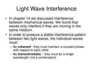
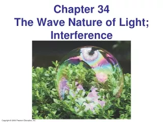
34-5 Interference in Thin Films Another way path lengths can differ, and waves interfere, is if they travel through different media. If there is a very thin film of material – a few wavelengths thick – light will reflect from both the bottom and the top of the layer, causing interference. This can be seen in soap bubbles and oil slicks.
34-5 Interference in Thin Films The wavelength of the light will be different in the oil and the air, and the reflections at points A and B may or may not involve phase changes.
34-5 Interference in Thin Films A similar effect takes place when a shallowly curved piece of glass is placed on a flat one. When viewed from above, concentric circles appear that are called Newton’s rings.
34-5 Interference in Thin Films A beam of light reflected by a material with index of refraction greater than that of the material in which it is traveling, changes phase by 180° or ½ cycle.
34-5 Interference in Thin Films Example 34-7: Thickness of soap bubble skin. A soap bubble appears green (λ = 540 nm) at the point on its front surface nearest the viewer. What is the smallest thickness the soap bubble film could have? Assume n = 1.35.
34-5 Interference in Thin Films • Problem Solving: Interference • Interference occurs when two or more waves arrive simultaneously at the same point in space. • Constructive interference occurs when the waves are in phase. • Destructive interference occurs when the waves are out of phase. • An extra half-wavelength shift occurs when light reflects from a medium with higher refractive index.
34-5 Interference in Thin Films Example 34-8: Nonreflective coating. What is the thickness of an optical coating of MgF2 whose index of refraction is n = 1.38 and which is designed to eliminate reflected light at wavelengths (in air) around 550 nm when incident normally on glass for which n = 1.50?
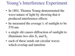
Summary of Chapter 34 • The wave theory of light is strengthened by the interference and diffraction of light. • Huygens’ principle: every point on a wave front is a source of spherical wavelets. • Wavelength of light in a medium with index of refraction n: • Young’s double-slit experiment demonstrated interference.
Summary of Chapter 34 • In the double-slit experiment, constructive interference occurs when • and destructive interference when • Two sources of light are coherent if they have the same frequency and maintain the same phase relationship.
Summary of Chapter 34 • Interference can occur between reflections from the front and back surfaces of a thin film. • Light undergoes a 180° phase change if it reflects from a medium of higher index of refraction.
Units of Chapter 35 • Diffraction by a Single Slit or Disk • Intensity in Single-Slit Diffraction Pattern • Diffraction in the Double-Slit Experiment • Limits of Resolution; Circular Apertures • Resolution of Telescopes and Microscopes; the λ Limit • Resolution of the Human Eye and Useful Magnification • Diffraction Grating
Units of Chapter 35 • The Spectrometer and Spectroscopy • Peak Widths and Resolving Power for a Diffraction Grating • X-Rays and X-Ray Diffraction • Polarization • Liquid Crystal Displays (LCD) • Scattering of Light by the Atmosphere
35-1 Diffraction by a Single Slit or Disk If light is a wave, it will diffract around a single slit or obstacle.
35-1 Diffraction by a Single Slit or Disk The resulting pattern of light and dark stripes is called a diffraction pattern.
35-1 Diffraction by a Single Slit or Disk This pattern arises because different points along a slit create wavelets that interfere with each other just as a double slit would.
35-1 Diffraction by a Single Slit or Disk The minima of the single-slit diffraction pattern occur when
35-1 Diffraction by a Single Slit or Disk Example 35-1: Single-slit diffraction maximum. Light of wavelength 750 nm passes through a slit 1.0 x 10⁻³ mm wide. How wide is the central maximum (a) in degrees, and (b) in centimeters, on a screen 20 cm away?
35-1 Diffraction by a Single Slit or Disk Conceptual Example 35-2: Diffraction spreads. Light shines through a rectangular hole that is narrower in the vertical direction than the horizontal. (a) Would you expect the diffraction pattern to be more spread out in the vertical direction or in the horizontal direction? (b) Should a rectangular loudspeaker horn at a stadium be high and narrow, or wide and flat?
35-2 Intensity in Single-Slit Diffraction Pattern Light passing through a single slit can be divided into a series of narrower strips; each contributes the same amplitude to the total intensity on the screen, but the phases differ due to the differing path lengths: .
35-2 Intensity in Single-Slit Diffraction Pattern . Finally, we have the phase difference and the intensity as a function of angle: and
35-2 Intensity in Single-Slit Diffraction Pattern Example 35-3: Intensity at secondary maxima. Estimate the intensities of the first two secondary maxima to either side of the central maximum.
35-3 Diffraction in the Double-Slit Experiment The double-slit experiment also exhibits diffraction effects, as the slits have a finite width. This means the amplitude at an angle θ will be modified by the same factor as in the single-slit experiment: The intensity is, as usual, proportional to the square of the field.
35-3 Diffraction in the Double-Slit Experiment The diffraction factor (depends on β) appears as an “envelope” modifying the more rapidly varying interference factor (depends on δ).
35-3 Diffraction in the Double-Slit Experiment Example 35-4: Diffraction plus interference. Show why the central diffraction peak shown, plotted for the case where d = 6D = 60λ, contains 11 interference fringes.
35-6 Resolution of the Human Eye and Useful Magnification The human eye can resolve objects that are about 1 cm apart at a distance of 20 m, or 0.1 mm apart at the near point. This limits the useful magnification of a light microscope to about 500x–1000x.
35-7 Diffraction Grating A diffraction grating consists of a large number of equally spaced narrow slits or lines. A transmission grating has slits, while a reflection grating has lines that reflect light. The more lines or slits there are, the narrower the peaks.
35-7 Diffraction Grating The maxima of the diffraction pattern are defined by
35-7 Diffraction Grating Example 35-8: Diffraction grating: lines. Determine the angular positions of the first- and second-order maxima for light of wavelength 400 nm and 700 nm incident on a grating containing 10,000 lines/cm.
35-8 The Spectrometer and Spectroscopy A spectrometer makes accurate measurements of wavelengths using a diffraction grating or prism.
35-8 The Spectrometer and Spectroscopy The wavelength can be determined to high accuracy by measuring the angle at which the light is diffracted:
35-8 The Spectrometer and Spectroscopy Atoms and molecules can be identified when they are in a thin gas through their characteristic emission lines.
35-8 The Spectrometer and Spectroscopy Example 35-11: Hydrogen spectrum. Light emitted by hot hydrogen gas is observed with a spectroscope using a diffraction grating having 1.00 x 10⁴ lines/cm. The spectral lines nearest to the center (0°) are a violet line at 24.2°, a blue line at 25.7°, a blue-green line at 29.1°, and a red line at 41.0° from the center. What are the wavelengths of these spectral lines of hydrogen?
35-9 Peak Widths and Resolving Power for a Diffraction Grating These two sets of diagrams show the phasor relationships at the central maximum and at the first minimum for gratings of two and six slits.
35-9 Peak Widths and Resolving Power for a Diffraction Grating As the number of slits becomes large, the width of the central maximum becomes very narrow: The resolving power of a diffraction grating is the minimum difference between wavelengths that can be distinguished:
35-9 Peak Widths and Resolving Power for a Diffraction Grating Example 35-12: Resolving two close lines. Yellow sodium light, which consists of two wavelengths, λ1 = 589.00 nm and λ2 = 589.59 nm, falls on a diffraction grating. Determine (a) the maximum order m that will be present for sodium light, and (b) the width of grating necessary to resolve the two sodium lines.
35-10 X-Rays and X-Ray Diffraction The wavelengths of X-rays are very short. Diffraction experiments are impossible to do with conventional diffraction gratings. Crystals have spacing between their layers that is ideal for diffracting X-rays.
35-10 X-Rays and X-Ray Diffraction X-ray diffraction is now used to study the internal structure of crystals; this is how the helical structure of DNA was determined.
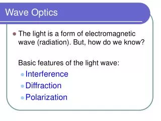
35-11 Polarization Light is polarized when its electric fields oscillate in a single plane, rather than in any direction perpendicular to the direction of propagation.
35-11 Polarization Polarized light will not be transmitted through a polarized film whose axis is perpendicular to the polarization direction.
35-11 Polarization When light passes through a polarizer, only the component parallel to the polarization axis is transmitted. If the incoming light is plane-polarized, the outgoing intensity is:
35-11 Polarization This means that if initially unpolarized light passes through crossed polarizers, no light will get through the second one.
35-11 Polarization Example 35-13: Two Polaroids at 60°. Unpolarized light passes through two Polaroids; the axis of one is vertical and that of the other is at 60° to the vertical. Describe the orientation and intensity of the transmitted light.
35-11 Polarization Conceptual Example 35-14: Three Polaroids. When unpolarized light falls on two crossed Polaroids (axes at 90°), no light passes through. What happens if a third Polaroid, with axis at 45° to each of the other two, is placed between them?
35-11 Polarization Light is also partially polarized after reflecting from a nonmetallic surface. At a special angle, called the polarizing angle or Brewster’s angle, the polarization is 100%: .
35-11 Polarization Example 35-15: Polarizing angle. (a) At what incident angle is sunlight reflected from a lake plane-polarized? (b) What is the refraction angle?
35-13 Scattering of Light by the Atmosphere Skylight is partially polarized due to scattering from molecules in the air. The amount of polarization depends on the angle that your line of sight makes with the Sun.
Summary of Chapter 35 • Light bends around obstacles and openings in its path, yielding diffraction patterns. • Light passing through a narrow slit will produce a central bright maximum of width • Minima occur at
Summary of Chapter 35 • Diffraction limits the resolution of images. • Diffraction grating has many parallel slits or lines; peaks of constructive interference are given by • Polarized light has its electric field vectors in a single plane.