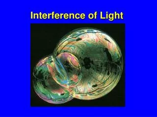
Light Wave Interference
Light Wave Interference. In chapter 14 we discussed interference between mechanical waves. We found that waves only interfere if they are moving in the same medium. In order to produce a stable interference pattern between two light waves, the individual waves must:

Light Wave Interference
E N D
Presentation Transcript
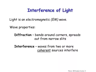
Light Wave Interference • In chapter 14 we discussed interference between mechanical waves. We found that waves only interfere if they are moving in the same medium. • In order to produce a stable interference pattern between two light waves, the individual waves must: • Be coherent - they must maintain a constant phase with respect to each other. • Be monochromatic – they must be a single wavelength (not a combination)
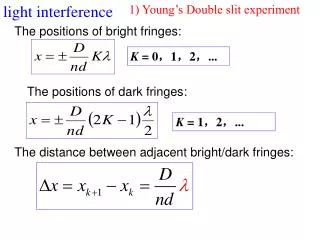
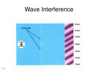
Young’s Double-Slit Experiment • The two slits act as a pair of coherent light sources because waves emerging from the slits originated from the same wave front and therefore have the same properties. • When these waves overlap, interference patterns appear. • This experiment demonstrated that light acts as a wave.
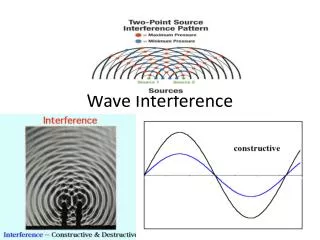
Model of Wave Interference • The light from S1 and S2 produces a visible pattern of bright and dark parallel bands called fringes. • When constructive interference occurs, a bright fringe appears. • When destructive interference occurs, a dark fringe appears.
Light Intensity versus Path Difference Constructive interference Destructive interference m is the “order number”
Geometric construction of the double-slit experiment Path difference
Combining everything… • Even though the waves are in phase at the slits, they travel a different distance to the screen so at the screen there is a phase difference between the interfering waves. • Intensity (brightness) at a point P
Lloyd’s Mirror • An interference pattern is produced at point P on the screen as a result of the combination of the direct ray (blue) and the reflected ray (brown). The reflected ray undergoes a phase change of 180°.
Lloyd’s Mirror • To solve this type of problem, treat it as a 2-slit problem where the phase difference at the screen is 180°. • Due to the set-up of this problem, we will have an inverted interference pattern on the screen. • A dark central minimum at P’ and alternating bright and dark spots spreading from that point. • To solve for a bright/dark spot use the ydark/ybright equations.
Boundary Reflection • (a) For n1 < n2, a light ray traveling in medium 1 when reflected from the surface of medium 2 undergoes a 180° phase change. The same thing happens with a reflected pulse traveling along a string fixed at one end. • (b) For n1 > n2, a light ray traveling in medium 1 undergoes no phase change when reflected from the surface of medium 2. The same is true of a reflected wave pulse on a string whose supported end is free to move.
Interference in Thin Films • Light interference in thin films is due to a combination of rays 1 and 2 reflected from the upper and lower surfaces of the film. • Rays 3 and 4 lead to interference effects for light transmitted through the film. • Constructive Interference • Destructive Interference
Diffraction • Occurs when waves pass through small openings, around obstacles, or past sharp edges. • The resulting shadow pattern is called a diffraction pattern. • We will focus on the Fraunhofer Diffraction Pattern – this is produced when light passes through a narrow opening.
Diffraction of light • When we discussed interference, we assumed the slits acted like point sources of light. Now we will no longer assume slits are point sources of light. We will now consider how the finite width of the slit affects the light and creates a diffraction pattern. • Each portion of the slit acts as a point source of light waves.
Diffraction of light • Always divide the slit into two halves for convenience • Always remember the waves are all in phase as they leave the slit, • but as they travel different distances to the screen, they move out of phase causing interference.
Deriving Equations… • We already know the equation for destructive interference from the last chapter • This equation gives q for when the diffraction pattern has a dark fringe (zero intensity).
Resolution • Rayleigh’s Criterion • When the central maximum of one image falls on the first minimum of the other image, the images are said to be “just resolved.” • Minimum angular separation for single-slit resolution: • Minimum angular separation for a circular aperture resolution:
Rayleigh’s Criterion – single slit Resolved Not Resolved
Rayleigh’s Criterion – circular aperture Just resolved
Diffraction Grating • A useful device for analyzing light sources, consists of a large # of equally spaced parallel slits. • Gratings ruled 5000 lines/cm have a slit spacing: d = 1/5000. • Just like all our other situations, the waves start out in phase and by the time they reach the screen they’ve traveled different distances and so they interfere.
Diffraction Grating • Diffraction grating is most useful for measuring wavelengths because it can be used like a prism and it will disperse a spectrum. • For two nearly equal wavelengths, between which a diffraction grating can barely distinguish, the resolvingpower of the grating is:
Diffraction of x-rays by crystals • In principle, the wavelengths of any EM wave can be determined if the proper diffraction grating is available. • But x-rays have such a small wavelength that is it impossible to create a diffraction grating with small enough slits. • Atomic spacing is just the right size for x-rays. • Constructive maxima occur: • This is called Bragg’s Law. It is most often used to calculate d, the atomic spacing.