Interference and Diffraction
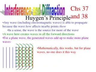
Interference and Diffraction. Wave Optics. The wave nature of light is needed to explain various phenomena Interference Diffraction The particle nature of light was the basis for ray (geometric) optics Light waves interfere with each other much like mechanical waves do

Interference and Diffraction
E N D
Presentation Transcript
Wave Optics • The wave nature of light is needed to explain various phenomena • Interference • Diffraction • The particle nature of light was the basis for ray (geometric) optics • Light waves interfere with each other much like mechanical waves do • All interference associated with light waves arises when the electromagnetic fields that constitute the individual waves combine
Conditions for Interference • For interference between two sources of light to be observed, there are two conditions which must be met • The sources must be coherent • They must maintain a constant phase with respect to each other • The waves must have identical wavelengths
Producing Coherent Sources • Old method • Light from a monochromatic source is allowed to pass through a narrow slit • The light from the single slit is allowed to fall on a screen containing two narrow slits • The first slit is needed to insure the light comes from a tiny region of the source which is coherent • Currently, it is much more common to use a laser as a coherent source • The laser produces an intense, coherent, monochromatic beam over a width of several millimeters • The laser light can be used to illuminate multiple slits directly
Young’s Double Slit Experiment • Thomas Young first demonstrated interference in light waves from two sources in 1801 • Light is incident on a screen with a narrow slit, So • The light waves emerging from this slit arrive at a second screen that contains two narrow, parallel slits, S1 and S2 • The narrow slits, S1 and S2 act as sources of waves • The waves emerging from the slits originate from the same wave front and therefore are always in phase
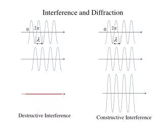
Resulting Interference Pattern • The light from the two slits form a visible pattern on a screen • The pattern consists of a series of bright and dark parallel bands called fringes • Constructive interference occurs where a bright fringe appears • Destructive interference results in a dark fringe
Interference Patterns • Constructive interference occurs at the center point • The two waves travel the same distance • Therefore, they arrive in phase
Interference Patterns, 2 • The upper wave has to travel farther than the lower wave • The upper wave travels one wavelength farther • Therefore, the waves arrive in phase • A bright fringe occurs
Interference Patterns, 3 • The upper wave travels one-half of a wavelength farther than the lower wave • The trough of the bottom wave overlaps the crest of the upper wave • This is destructive interference • A dark fringe occurs
InterferenceEquations • The path difference, δ, is found from the tan triangle • δ = r2 – r1 = d sin θ • This assumes the paths are parallel • Not exactly parallel, but a very good approximation since L >> d • For a bright fringe, produced by constructive interference, the path difference must be either zero or some integral multiple of the wavelength • δ = d sin θbright = mλ • m = 0, ±1, ±2, … • m is called the order number • When m = 0, it is the zeroth order maximum • When m = ±1, it is called the first order maximum
Interference Equations, 2 • The positions of the fringes can be measured vertically from the zeroth order maximum • y = L tan θL sin θ • Assumptions • L>>d • d>>λ • Approximation • θ is small and therefore the approximation tan θsin θ can be used • When destructive interference occurs, a dark fringe is observed • This needs a path difference of an odd half wavelength • δ = d sin θdark = (m + ½) λ • m = 0, ±1, ±2, …
Interference Equations, final • For bright fringes • For dark fringes
Uses for Young’s Double Slit Interference • Young’s Double Slit Experiment provides a method for measuring wavelength of the light • This experiment gave the wave model of light a great deal of credibility • It is inconceivable that particles of light could cancel each other
Phase Changes Due To Reflection • An electromagnetic wave undergoes a phase change of 180° upon reflection from a medium of higher index of refraction than the one in which it was traveling • Analogous to a reflected pulse on a string
Phase Changes Due To Reflection, cont • There is no phase change when the wave is reflected from a boundary leading to a medium of lower index of refraction • Analogous to a pulse in a string reflecting from a free support
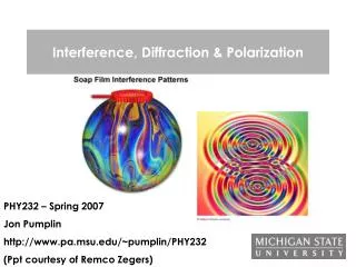
Interference in Thin Films • Interference effects are commonly observed in thin films • Examples are soap bubbles and oil on water • The interference is due to the interaction of the waves reflected from both surfaces of the film • Facts to remember • An electromagnetic wave traveling from a medium of index of refraction n1 toward a medium of index of refraction n2 undergoes a 180° phase change on reflection when n2 > n1 • There is no phase change in the reflected wave if n2 < n1 • The wavelength of light λn in a medium with index of refraction n is λn = λ/n where λ is the wavelength of light in vacuum
Interference in Thin Films, 2 • Ray 1 undergoes a phase change of 180° with respect to the incident ray • Ray 2, which is reflected from the lower surface, undergoes no phase change with respect to the incident wave • Ray 2 also travels an additional distance of 2t before the waves recombine • For constructive interference • 2nt = (m + ½ ) λm = 0, 1, 2 … • This takes into account both the difference in optical path length for the two rays and the 180° phase change • For destruction interference • 2 nt = mλm = 0, 1, 2 …
Interference in Thin Films, 3 • Two factors influence interference • Possible phase reversals on reflection • Differences in travel distance • The conditions are valid if the medium above the top surface is the same as the medium below the bottom surface • If the thin film is between two different media, one of lower index than the film and one of higher index, the conditions for constructive and destructive interference are reversed • Be sure to include two effects when analyzing the interference pattern from a thin film • Path length • Phase change
Newton’s Rings • Another method for viewing interference is to place a planoconvex lens on top of a flat glass surface • The air film between the glass surfaces varies in thickness from zero at the point of contact to some thickness t • A pattern of light and dark rings is observed • This rings are called Newton’s Rings • The particle model of light could not explain the origin of the rings • Newton’s Rings can be used to test optical lenses
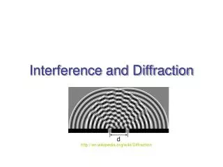
Diffraction • Huygens ‘principle requires that the waves spread out after they pass through slits • This spreading out of light from its initial line of travel is called diffraction • In general, diffraction occurs when waves pass through small openings, around obstacles or by sharp edges
Diffraction, 2 • A single slit placed between a distant light source and a screen produces a diffraction pattern • It will have a broad, intense central band • The central band will be flanked by a series of narrower, less intense secondary bands • Called secondary maxima • The central band will also be flanked by a series of dark bands • Called minima • The results of the single slit cannot be explained by geometric optics • Geometric optics would say that light rays traveling in straight lines should cast a sharp image of the slit on the screen
Fraunhofer Diffraction • Fraunhofer Diffraction occurs when the rays leave the diffracting object in parallel directions • Screen very far from the slit • Converging lens (shown) • A bright fringe is seen along the axis (θ = 0) with alternating bright and dark fringes on each side
Single Slit Diffraction • Huygens’ principle: each portion of the slit acts as a source of waves • The light from one portion of the slit can interfere with light from another portion • The resultant intensity on the screen depends on the direction θ • All the waves that originate at the slit are in phase • Wave 1 travels farther than wave 3 by an amount equal to the path difference (a/2) sin θ • If this path difference is exactly half of a wavelength, the two waves cancel each other and destructive interference results
Single Slit Diffraction, 2 • In general, destructive interference occurs for a single slit of width a when sin θdark = mλ / a • m = 1, 2, 3, … • Doesn’t give any information about the variations in intensity along the screen • The general features of the intensity distribution are shown • A broad central bright fringe is flanked by much weaker bright fringes alternating with dark • The points of constructive interference lie approximately halfway between the dark fringes
Diffraction Grating • The diffracting grating consists of many equally spaced parallel slits • A typical grating contains several thousand lines per centimeter • The intensity of the pattern on the screen is the result of the combined effects of interference and diffraction
Diffraction Grating, cont • The condition for maxima is • d sin θbright = mλ • m = 0, 1, 2, … • The integer m is the order number of the diffraction pattern • If the incident radiation contains several wavelengths, each wavelength deviates through a specific angle
Diffraction Grating, final • All the wavelengths are focused at m = 0 • This is called the zeroth order maximum • The first order maximum corresponds to m = 1 • Note the sharpness of the principle maxima and the broad range of the dark area • This is in contrast to the broad, bright fringes characteristic of the two-slit interference pattern
Resolution • The ability of an optical system to distinguish between closely spaced objects is limited due to the wave nature of light • If two sources of light are close together, they can be treated as non-coherent sources • Because of diffraction, the images consist of bright central regions flanked by weaker bright and dark rings
Rayleigh’s Criterion • If the two sources are separated so that their central maxima do not overlap, their images are said to be resolved • The limiting condition for resolution is Rayleighs’ Criterion • When the central maximum of one image falls on the first minimum of another image, they images are said to be just resolved • The images are just resolved when their angular separation satisfies Rayleigh’s criterion • For a slit of width a, and applying Rayleighs’ criterion, the limiting angle of resolution is • For the images to be resolved, the angle subtended by the two sources at the slit must be greater than θmin
Resolution with Circular Apertures • The diffraction pattern of a circular aperture consists of a central, circular bright region surrounded by progressively fainter rings • The limiting angle of resolution depends on the diameter, D, of the aperture; by integrating over the circle one obtains
Resolving Power of a Diffraction Grating • If λ1 and λ2 are nearly equal wavelengths between which the grating spectrometer can just barely distinguish, the resolving power, R, of the grating is • A grating with a high resolving power can distinguish small differences in wavelength • The resolving power increases with order number • R = Nm • N is the number of lines illuminated • m is the order number • All wavelengths are indistinguishable for the zeroth-order maximum • m = 0 so R = 0