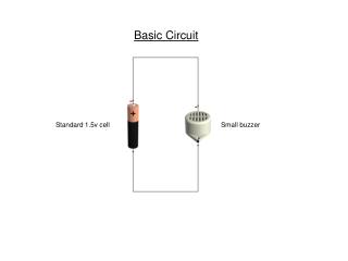
INC 112 Basic Circuit Analysis
INC 112 Basic Circuit Analysis. Week 8 RL Circuits. First-order Differential equation. Objective: Want to solve for i(t) (in term of function of t). RL Circuit. KVL. Voltage source go to zero. consider. Assume that i(t) = g(t) make this equation true.

INC 112 Basic Circuit Analysis
E N D
Presentation Transcript
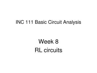
INC 112 Basic Circuit Analysis Week 8 RL Circuits
First-order Differential equation Objective: Want to solve for i(t) (in term of function of t) RL Circuit KVL
Voltage source go to zero consider Assume that i(t) = g(t) make this equation true. However, g(t) alone may be incomplete. The complete answer is i(t) = f(t) + g(t) where f(t) is the answer of the equation
i(t) consists of two parts Forced Response Transient Response Therefore, we will study source-free RL circuit first
Source-free RL Circuit Inductor L has energy stored so that the initial current is I0 Compare this with a pendulum with some height (potential energy) left. height
There are 2 ways to solve first-order differential equations
Method 1: Assume solution where A and s is the parameters that we want to solve for Substitute in the equation ซึ่งเทอมที่จะเป็น 0 ได้ก็คือเทอม (s+R/L) เท่านั้น ดังนั้นจะได้ คำตอบจะอยู่ในรูป
Initial condition Substitute t=0, i(t=0)=0 from We got
Natural Response of RL circuit i(t) I0 Approach zero t Natural Response only
Time Constant Ratio L/R is called “time constant”, symbol τ Unit: second Time constant is defined as the amount of time used for changing from the maximum value (100%) to 36.8%.
Forced Response Natural Response i(t) 2A 1A Approach 1A t Forced response = 1A comes from voltage source 1V Natural Response + Forced Response
t < 0 Switch Open at t =0 Close at t =0 3-way switch
Switch Open at t =0 Close at t =0 t > 0 3-way switch
v(t) v(t) 1V 1V 0V 0V t t Step function (unit)
Will divide the analysis into two parts: t<0 and t>0 When t<0, the current is stable at 2A. The inductor acts like a conductor, which has some energy stored. When t>0, the current start changing. The inductor discharges energy. Using KVL, we can write an equation of current with constant power supply = 1V with initial condition (current) = 2A
Forced Response Natural Response We can find c2 from initial condition i(0) = 2 A Substitute t = 0, i(0) = 2 Therefore, we have Substitute V=1, R=1
RL Circuit Conclusion • Force Response of a step input is a step • Natural Response is in the form • where k1 is a constant, whose value depends on • the initial condition.
How to Solve Problems? • Start by finding the current of the inductor L first • Assume the response that we want to find is in form of • Find the time constant τ (may use Thevenin’s) • Solve for k1, k2 using initial conditions and • status at the stable point • From the current of L, find other values that the problem ask
Example The switch is at this position for a long time before t=0 , Find i(t) Time constant τ = 1 sec
At t=0, i(0) = 2 A At t = ∞, i(∞) = 1 A Therefore, k1 = 1, k2 = 1 The answer is
2A 1A
Example L has an initial current of 5A at t=0 Find i2(t) The current L is in form of Time constant = R/L, find Req (Thevenin’s) Time constant
Find k1, k2 using i(0) = 5, i(∞) = 0 At t=0, i(0) = 5 A At t = ∞, i(∞) = 0 A Therefore, k1=0, k2 = 5 i2(t) comes from current divider of the inductor current Graph?
Example L stores no energy at t=0 Find v1(t) Find iL(t) first
Find k1, k2 using i(0) = 0, i(∞) = 0.25 At t=0, i(0) = 0 A At t = ∞, i(∞) = 0.25 A Therefore, k1=0.25, k2 = -0.25 v1(t) = iL(t) R Graph?