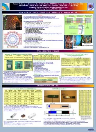
CMS ME CSC HV system
CMS ME CSC HV system. Alex Madorsky University of Florida. Cathode Strip Chambers. Main purpose of the CMS EMU CSC HV system: Provide High Voltage for CMS Endcap Muon Cathode Strip Chambers (CSC) CSC features that affect HV system design: Small HV segments – high tolerance to HV failures

CMS ME CSC HV system
E N D
Presentation Transcript
CMS ME CSC HV system Alex Madorsky University of Florida
Cathode Strip Chambers • Main purpose of the CMS EMU CSC HV system: • Provide High Voltage for CMS Endcap Muon Cathode Strip Chambers (CSC) • CSC features that affect HV system design: • Small HV segments – high tolerance to HV failures • Same working voltage with small variations from segment to segment • Problematic segment can be fixed by: • Reducing voltage • Disconnecting from HV • Needs precise consumption current measurement for each segment One HV segment Alex Madorsky
Voltage and current parameters • Voltage: • The operational point 3.6 kV (full efficiency) • The end of plateau is at 3.9 kV • Current: • Current per channel averaged over the full Encap Muon System: ~0.7 uA/segment • Maximum expected current per segment: 2uA • Needs to be monitored on each segment with good precision, to detect possible troubles. Alex Madorsky
UF/PNPI design • UF/PNPI HV system design: • 3.5 years of development • 3 prototypes + pre-production prototype produced • Prototypes passed all tests Alex Madorsky
Target specifications (1) Alex Madorsky
Target specifications (2) Alex Madorsky
Target specifications (3) Alex Madorsky
Target specifications (4) • System structure defined by us • Master HV sources and control computers in Control Room • Voltage regulation and monitoring, current measurement by Distribution boards near disks Alex Madorsky
Target specifications (5) • Two types of distribution boards: • 36 channels (two small chambers) • 30 channels (one large chamber) • Output connector defined by us. Alex Madorsky
UF/PNPI HV system architecture Multiwire HV cables, 100 m, one per 18 distribution boards • Primary HV power supplies: off the shelf • Master board: One output per distribution board. Regulates voltage 0-4KV (VMAX), measures current on each output. • Remote Distribution board: powers one large or two small chambers (36 outputs max). Regulates voltage 1KV down from VMAX, measures current on each output. Each output can be disconnected from HV if necessary. Alex Madorsky
Control interface Alex Madorsky
US CMS Review • Conducted on June 24th 2003 in UF • UF/PNPI system selected over CAEN • Reasons: • Price • Design features: • Simple and robust design • No programmable logic in radiation – no SEU Alex Madorsky
UF/ PNPI CMS EMU CSC HV System Main Design Features • Main technical approaches are shown • HV regulator • Current sensor • Fuse control • Digital control interface • Mechanical design Alex Madorsky
HV regulator (distribution board) • Output voltage controlled by linear regulator (Q1) • Regulates down to –1000V from input voltage • Voltage measured by divider R1-R2 and U1A opamp. • Regulator feedback via U2A • Q2 and C1 provide HV decoupling Alex Madorsky
Current sensor I U=IRs R2 R3 Rs Cv=KU D1 Ug C1 C2 CHARGE SENSITIVE AMP. R4 Q=UgCv U3A Uout + - R5 Cf • Current measured across Rs • Varicap D1 is used as voltage-sensitive element • Input pulse is applied via C1 • U3A is a charge-sensitive amplifier Uout=QCf=UgCvKuIRsCf=KI Alex Madorsky
Fuse control • Situation requiring permanent disconnect is extremely rare (never happened on FAST sites) • Fuse is used to disconnect channel from HV permanently • To blow fuse: • Low negative voltage applied to channel input • Switch Q3 shorted • Fuse can be quickly replaced during short access Alex Madorsky
Control interface • Differential signal transmission (RS-485) • Optically insulated • Built completely on discrete logic Alex Madorsky
Control software • Based on PVSS and DIM server • Initial version of DIM server and PVSS shell works • Written with excellent assistance of Valery Sytnik (UC Riverside) • Targeted for full DCS compatibility • Work in progress Alex Madorsky
Mechanical construction • Final mechanical construction • Simple and rugged design • PCB is optimized for automatic assembly Alex Madorsky
Distribution Rack Fan unit & heat exchanger • Need from CMS: • Racks • Fan units & heat exchangers • Strain reliefs • Space in front and behind the racks • Low Voltage power for distribution boards Distribution crate Distribution boards HV and control cables patch panel Output HV cables to chambers Alex Madorsky
Distribution Racks • In the table above: • 9x30 means 9 boards of 30 channels. One board of 30 channels powers one ME23/2 chamber • 9x36 means 9 boards of 36 channels. One board of 36 channels powers two ME23/1 (or similar) chambers • This table shows the HV distribution boards necessary for one Endcap (+ or -). Alex Madorsky
Rack position for YE1 and YE2 YE1 has only one rack Alex Madorsky
Low Voltage Requirements for Remote Distribution Cards • Low voltage power will be provided by CMS AC/DC LV system Alex Madorsky
Cooling • Only remote distribution racks are discussed. • Dissipated heat: • 4.8 W maximum per distribution board (about 3-4% of one chamber LV power) • ~216 W per rack maximum (45 boards) • ~1335 W for all distribution boards • Cooling of distribution boards: • No enforced cooling is currently planned • Racks must be open on top and bottom for convection • Need heat exchangers to remove generated heat • May need fans (unlikely, will decide later) Alex Madorsky
Safety • HV Cables • KERPEN halogen-free cables • Passed CERN flammability test • HV Connectors • LEMO/REDEL, bought from CERN stock • PCB material • FR-4, flammability rating 94-V0 • Other components • Will be checked for CERN safety compliance Alex Madorsky
Design status • Boards’ design complete (electrical and mechanical) • Pre-production prototype constructed in UF, under tests now • Tests of the pre-production prototype: • Full bench test – OK • Chamber test on FAST site – OK • Radiation test – OK • Magnetic field test – November ’03 • Production boards - exact copy of the pre-production prototype Alex Madorsky
UF-PNPI collaboration • MOU between UF and PNPI is signed • Arrangement is very similar to chamber production • UF responsibility: • Development and production management • Pre-production prototype construction and testing • Test stands construction • Test procedures verification, instructions • Off-the-shelf components procurement • Bare PCBs manufacturing • Automated SMT assembly • US labor and components contingency Alex Madorsky
UF-PNPI collaboration • PNPI responsibility: • Simple mechanical components manufactured • Pre-production and production manual assembly • Pre-production and production testing • PNPI labor and space contingency Alex Madorsky
Schedule • ESR – November ’03 • Board production and SMT assembly start in US – end of November ’03 • Start of pre-production run in PNPI – end of January ’04 • Pre-production system test in UF – May ’04 • PNPI production readiness review, production start – July ’04 • Production finish – June ‘05 Alex Madorsky
Installation and commissioning • Installation: • To be done by CERN crew & UF/PNPI visitors • Will start as soon as the first shipment arrives to CERN (Oct 04’) • Very uncomplicated • 278 distribution boards, 30 crates • HV cables already installed by that time • Commissioning: • LV power supplies are necessary – at least prototype • Would like to start as early as possible (Oct ‘04) Alex Madorsky
Conclusions • Design solutions are proved to be working • Pre-production prototype built • Pre-production prototype passed tests • Satisfies CMS EMU CSC HV system specs • Production documentation is being prepared Alex Madorsky
Radiation environment • Expected: • Neutron Fluence: (1 - 4) x 10^10/sq cm • Total Ionizing Dose: ( 0.07 – 0. 7) kRad Alex Madorsky