Advanced PFC Design and Implementation for Fusion Reactor Systems
This document outlines the advanced requirements and design concepts for plasma-facing components (PFC) in fusion reactors, with a focus on carbon-based materials and innovative structural designs. Key provisions include the integration of NBI armor and divertor features, enhancements for thermal management, and flexibility for plasma shape optimization. The phased implementation plan covers initial coverage techniques and future adaptations, ensuring a structure accommodating thermal and energetic particle fluxes, while maintaining effective cooling and diagnostics. Full surface coverage through carbon fiber composite technology is also prioritized.

Advanced PFC Design and Implementation for Fusion Reactor Systems
E N D
Presentation Transcript
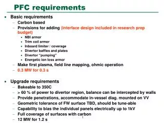
PFC requirements • Basic requirements • Carbon based • Provisions for adding (interface design included in research prep budget) • NBI armor • Trim coil armor • Inboard limiter / coverage • Divertor baffles and plates • Divertor “pumping” • Energetic ion loss armor • Make first plasma, field line mapping, ohmic operation • 0.3 MW for 0.3 s • Upgrade requirements • Bakeable to 350C • > 60 % of power to divertor region, balance can be intercepted by walls • Provide penetrations, accommodate in-vessel diag. mounted on VV • Geometric tolerance of FW surface TBD, should be tune-able • Capability to bias the individual panels electrically up to 1kV • Full coverage of surfaces with carbon • 12 MW for 1.2 s
PFC envelope maximized inside vessel • PFC envelope is pushed out to vessel wall to provide maximum plasma shape flexibility • Divertor envelope is still evolving, but baffles for neutral particle control must be accommodated PFC envelope PFC envelope with plasma
PFC design concept Poloidal ribs • Staged implementation planned • Initial coverage with carbontiles mounted on vessel assembly flanges to form array of poloidal limiters • Panels for NB armorand divertor region will also be provided after NBI installed • Full coverage provided by mounting molded carbon fiber composite (CFC) panels on poloidal ribs • Panel size based on advice from BFG aerospace (~ 60 cm square, 1 cm thick) • Ribs are separately cooled / heated with He gas for bakeout (350C) and normal operation • Ribs are registered toroidally to VV but allowed to grow radially and vertically CFC panels mounted on poloidal ribs
PFC panel / rib detail • Details for one concept for panel attachment developed with BFG Aerospace Plasma Panel installed Panel ass’y retracted Thermally insulated connection to vessel Heated / Cooled Rib Vacuum vessel
Project cost: Program cost: PFC implementation plan
PFC implementation: Phases I, II, III • NO Rib structure with cooling/heating lines • Carbon (e.g. Poco, ATJ) tiles mounted directly to VV • Carbon limiters are installed only at v=1/2 (bullet) cross section, but are semi-continuous poloidally
PFC simple limiter detail • Details for flat carbon plates at either side of bullet shaped section (vessel field joint) Plasma Spacer at bullet section Carbon plate Tee nut Joint stud Stand-off Vacuum vessel
Heat loads on limiter • Assume: • 1 cm e-folding of particle energy • 0.3 MW per pulse • 6 toroidal locations to remove heat • Poloidal peaking factor of 20 • Max flux = 2275 W/cm^2
Heat flux limit on isolated limiter tile • 1-D calculation • Ratcheting limit assumes radiation cooling only • 10 minute cool-down between pulses • 1200 C max temperature Operating point
Plasma (a) (b) PFC implementation: Phase IV • Rib structure with cooling/heating line • Panel coverage from upper divertor to lower divertor on inboard side • Panel coverage for NBI armor on outboard side • Exposed ribs protected with low Z coating: • B4C spray coating • Sheet metal covers with B4C coating
baffle pump (e.g. Ti-getter) divertor plate divertor pumping plenum First wall panel surface LCMS Z(m) PFC implementation: Phases V,VI • Phase V, divertor baffles • Phase VI, with active pump • Panel coverage everywhere? Ref. Peter Mioduszewski.