CERN SPS Upgrade
CERN SPS Upgrade. New 200 MHz and 800 MHz amplifiers. CERN Accelerator Complex. Protons and Lead Ions to maximum acceleration LINAC2 (proton) or Linac 3 (Lead ions) Booster (protons) or Leir (lead ions) PS (Proton Synchrotron) SPS (Super Proton Synchrotron)

CERN SPS Upgrade
E N D
Presentation Transcript
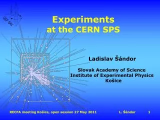
CERN SPS Upgrade New 200 MHz and 800 MHz amplifiers
CERN Accelerator Complex 15th ESLS-RF Workshop • Protons and Lead Ions to maximum acceleration • LINAC2 (proton) or Linac 3 (Lead ions) • Booster (protons) or Leir (lead ions) • PS (Proton Synchrotron) • SPS (Super Proton Synchrotron) • LHC (Large Hadron Collider) • Several other experiences : • n_TOF – The neutron time-of-flight facility; a neutron source that has been operating at CERN since 2001 • AD – The Antiproton Decelerator; manufacturing antimatter providing low-energy antiprotons for studies of antimatter • ISOLDE – Isotope Separator On-Line; source of low-energy beams of radioactive isotopes • CLIC – the Compact Linear Collider Study; an international collaboration working on a concept for a post LHC machine to collide electrons and positrons head on at energies up to several TeV
CERN SPS – the Super Proton Synchrotron North Experimental area SPS as LHC injector CNGS : CERN Neutrions to Gran Sasso 15th ESLS-RF Workshop • The second largest machine in CERN’s accelerator complex, nearly 7 km in circumference. It was switched on in 1976 (CERN Nobel-prize for discovery of W and Z particles in 1983) • Presently, SPS accelerates particles to provide beams for the: • FT (Fixed Target) program (North Area) • CNGS project • LHC (Large Hadron Collider) • And Many Machine Developments
200 MHz RF in the SPS 1975 1980 1990 2000 2010 1976 TWC#1 / TX1 TWC#2 / TX2 1979 TWC#4 / TX4 1980 TWC#1 / TX1+TX2 TWC#2 / TX3+TX4 TWC#3 / TX5+TX6 TWC#4 / TX7+TX8 1978 TWC#3 / TX3 Configuration of one of the four 200 MHz power plant Transmitter (TXA) Coaxial transmission line (feeder line) 125 to 160 meters Dummy load mW Terminating loads Power combiner Transmitter (TXB) Accelerating cavity 15th ESLS-RF Workshop • The RF-SPS started up in 1976 with two accelerating cavities • Since 1980, for the new role of SPS as proton-antiproton collider, there are four cavities operating @ 200 MHz • We have 4 lines : • 2 x Siemens: 20 x RS2004 • 2 x Philips: 68 x YL1530
Two ‘Siemens’ lines = 20 x RS2004 15th ESLS-RF Workshop
Two ‘Philips’ lines = 68 x YL1530 15th ESLS-RF Workshop
Travelling Wave Cavities • One section: 11 drift tubes • One 4 sections cavity 15th ESLS-RF Workshop • One section = 11 drift tubes • 2 x 4 sections Siemens plants • 2 x 5 sections Philips plants • 4 Main Power Couplers • 2 input couplers • 2 output couplers • 2 x 550 kW terminating power loads
200 MHz limitations Courtesy of Elena Shaposhnikova 15th ESLS-RF Workshop • With present 4 cavities configuration we will have problems at ultimate LHC current • The increased number of shorter cavities with 2 extra power plants should significantly improve the RF performance for ultimate LHC intensities • The best compromise is 6 cavities: • 4 x 3 sections cavities with 1.0 MW • 2 x 4 sections cavities with 1.4 MW • Total voltage possible on the flat top vs beam current with : • 4 cavities (present situation) with 1.0 MW • 5 cavities with 1.0 MW RF • 6 cavities with 4 x 1.0 MW + 2 x 1.4 MW • Dashed lines are at nominal and ultimate beam currents.
Cavities redistribution 15th ESLS-RF Workshop 2011 : 4 cavities 2 x 4 sections 2 x 5 sections + 3 spare sections 2018 : 6 cavities 2 x 4 sections 4 x 3 sections + 1 spare section
First upgrade: Present amplifiers Tetrodes: Present lifetime statistics, operating ~650 kW cw: RS2004 : 20’000 hrs : 6 tubes per year YL1530 : 25’000 hrs : 16 tubes per year HVPS need a full re-cabling and air cooling improvement to allow higher pulsed mode 15th ESLS-RF Workshop
New RF power plant New RF Building 1 mW 1.7 MW RF amplifier Coaxial transmission line 150 meters 1 mW 1.7 MW RF amplifier Accelerating cavity Accelerating cavity 15th ESLS-RF Workshop New RF Amplifier LSS3 Tunnel integration New RF Building
2018 : two new power amplifiers 15th ESLS-RF Workshop • Must be reliable: • 24/24 hours • 300/365 days (2 months winter Technical stop) • 20 years of operation, with 3 years of operation + 1 year off cycle • Pulse mode: 1.7 MW max • Average: 850 kW (thermal limitation) • 2 x 1.7 MW Klystron • 2 x 4 x 450 kW Diacrodes • 2 x 8 x 225 kW IOTs • 2 x 8 x 225 kW tetrodes • Equivalent to ‘Siemens’ • 2 x 16 x 110 kW tetrodes • Equivalent to ‘Philips’ • 2 x 1700 x 1 kW SSA
1.7 MW amplifier, i.e 1.4 MW cavity From Beam Control 1/16 splitter Drivers 16 SSA Final 16 Tubes or SSA 1.7 MW -0.6 dB total 3 dB combiners and power loads 1.5 MW 120 m and 180 m Coaxial lines -0.2 dB 1.4 MW To cavity input 120 m away 15th ESLS-RF Workshop • To have 1.4 MW available at the cavity input, 1.7 MW at the Final output are needed • Taking advantage of the long experience we have with tetrodes and combiners, a possible solution could be a 16 x tetrodes combined through 3 dB combiners • A major improvement to present systems would be to have individual SSA drivers per tetrodes • Four contracts : • Drivers (SSA) • Finals (SSA or Tetrodes) • Combiners (3 dB above 100 kW) • Transmission lines (coaxial, 345 mm outer)
SSA vs Tetrodes 15th ESLS-RF Workshop • Overdesign requirements : • 14/16 tubes shall provide full power, i.e. each tube shall deliver up to 138 kW • SSA are more ‘reliable’: 2000/2048 of the total number of devices shall deliver full power • Tetrodes tube costs over 20 years will be added : • 20 year * 3/4 * 335 * 24 = 120’000 total hours • With 20’000 hours per tube = ~ 200 tubes • Reduced by warranty lifetime • SSA obsolescence shall be integrated: • i.e. 20% additional transistors, not module, single chips (still under discussion, need experts inputs) • Wall plug efficiency will be part of the adjudication • HVPS included (Tetrodes) • Losses in all SSA combiners, circulators and loads included
New RF building 800 MHz RF workshop Siemens Faraday Cage Philips 15th ESLS-RF Workshop Only possible location is between two existing buildings Maximum ‘RF’ foot floor will be 2 x 450 m2 Whatever the solution, SSA or Tetrodes, the same building, no impact on the choice
Draft schedule Year 1 Year 2 Year 3 Year 4 Year 5 Year 6 Year 7 2011 2012 2013 2018 2014 2015 2016 2017 Cavities re-arrangement within a LS ( > 6 months) RF : Studies (amplifiers, couplers, cavities) Tendering MS Build new hardware Install Tunnel : Studies Commissioning Build New hardware Installation phase 1 (pickups + dampers + CV + EL + …) Installation phase 2 (cavities) Building: Studies Authorizations Building Services 15th ESLS-RF Workshop
200 MHZ upgrade Conclusions 15th ESLS-RF Workshop We will have two new 1.7 MW pulsed / 850 kW average RF power amplifiers Building will be the same, no impact The less expensive solution beetween SSA and Tetrode will be selected !
800 MHz RF in the SPS 15th ESLS-RF Workshop The proton beams for the LHC are intense and unless careful precautions are taken they become unstable in the SPS and cannot be accepted by the LHC One of the most important systems in the SPS used to keep the beams stable and of the highest quality is the 800 MHz RF system acting at the second harmonic of the main accelerating 200 MHz RF system This 800 MHz system in the SPS is essential for maintaining stability of the LHC beams. It is required at every point in the cycle from injection to extraction. It works by increasing the synchrotron frequency spread in the beam Stability is problematic above 1/5 nominal without the 800 MHz By applying RF voltages of ~ 1 MV (about 1/7 of the main RF system) via two cavities in the SPS ring this “Landau Damping” system increases the natural spread of synchrotron frequencies in the individual proton bunches, prevents them acting together, and thus ensures stability The RF power source and its ancillary equipment for this 800 MHz system must be of the highest reliability to ensure beams are available for the LHC at all times
Old 800 MHz system (1) 15th ESLS-RF Workshop • Since 1980, the system is composed of : • 2 Travelling Wave Cavities • 2 transmitters of 225 kW each connected via ~ 120m waveguides to the TWC • 4 x 56kW klystrons Valvo YK1198 per transmitter combined using 3 dB hybrids
Old 800 MHz system (2) 15th ESLS-RF Workshop • Unfortunately, that system has not been used for a very long time and has not been properly maintained. • We still only have : • 2 simultaneous klystrons available on 1 cavity • 6 operational klystrons • 10 broken klystrons (could be repaired for 100’000 $ each) • We also had major difficulties with power converter transformers : • 9/9 burnt • 4 repaired
Upgrade proposal One 800 MHz Line Layout One 240 kW Transmitter Layout RF Power Amplifier 60 kW cw Splitter Amplifiers Monitoring and Controls Power converters Ø shifter Attenuator 3dB Combiner Power load RF Power Amplifier 60 kW cw Cavity and Transmitter Monitoring and Controls (CERN) Amplifiers Monitoring and Controls Power converters 3dB Combiner Ø shifter Attenuator Power load RF Power Amplifier 60 kW cw Amplifiers Monitoring and Controls Power converters Ø shifter Attenuator 3dB Combiner RF Power Amplifier 60 kW cw Amplifiers Terminating load Monitoring and Controls Power converters Cavity Ø shifter Attenuator waveguide line (125 meters ) Power load • New transmitters will include: • RF power amplifiers chain • Final amplifier IOT based • Individual power converters • Individual Monitoring and control compatible with CERN interface • In total it will be 8 + 1 transmitters • Replace Klystron Transmitters with IOT Transmitters and re-use all existing peripherals • Maximum power will be slightly increased up to 240 kW CW • BW-1dBwill be increased: • 1.0 MHz with Klystrons • 6.0 MHz with IOTs 15th ESLS-RF Workshop
Selected supplier : Electrosys 15th ESLS-RF Workshop Two companies per member state have been contacted (40 companies) Six companies have been compliant to our specifications Electrosys has been selected ‘Quasi’ off the shelves Transmitter Possibility to have Thales or e2v trolleys and tubes for the same price
Factory Acceptance Tests:various operational modes 15th ESLS-RF Workshop
Factory Acceptance Tests:Bandwidth Pmax = 61.0 kW Pmax -1dB = 47.5 kW BW-1dB = 7.0 MHz (-3/+4 MHz) 15th ESLS-RF Workshop Power Amplifier (Driver + Final) • Operating frequency : 800.888 MHz • Bandwidth at -1dB : 6.0 MHz (+/- 3.0 MHz) • CW output minimum power : 60 kW • Amplifier meets all requirements
Factory acceptance tests:Phase stability 15th ESLS-RF Workshop • Carrier f0 at mid power (30 kW)with additional - 20 dB power sweep • Fully fulfill specification
Factory acceptance tests:Power Sweep 0.1 Pmax 0.9 Pmax 15th ESLS-RF Workshop
Factory Acceptance Tests:conclusion 15th ESLS-RF Workshop • All factory acceptance tests have shown compliance respect to the specification, and even better : • Linearity • Monotonous • Phase stability • Maximum output power • All requirements were fulfilled (we repeated all the tests twice to confirm the results) • We checked modularity of the equipments • We controlled noise level • We checked protections: • driver output reflected power operated while making tests (due to over range power sweep) • Water cooling, air temperature, current limits, etc …
CERN Acceptance Tests 15th ESLS-RF Workshop Pre-series Amplifier has been integrated within CERN operational area All tests cycles have been done for 4 hours each, no trouble has been discovered
Long duration tests:CW mode 15th ESLS-RF Workshop • When we launch CW long duration tests, difficulties arose • While doing the test over six weeks, we were not able to obtain a stable operation • Maximum time slots were : • 115 hours : 1 • 66 hours : 2 • 33 hours : 5 • < 24 hours : 18 → Not stable enough in CW mode
Air temperature sensitivity 15th ESLS-RF Workshop • Transmitter has shown to be Temperature sensible : • Water Temp = 26.4 +/- 0.5 • Air Temps = 22.1 +/- 2.6 • Driver Gain = 6.7 % • Cold IOT = + 7.5 % to - 38 % • Hot IOT = +/- 4.9 % • Drivers are inverse temp, while IOT is direct Temp • Restart a cold IOT must be done readjusting the drive within the first three minutes • CERN LLRF will manage these variations
Long duration tests:Super Cycle mode 15th ESLS-RF Workshop To reduce average power and be closer to machine operation, we launched Super Cycle long duration tests, new difficulties arose While doing the test over four weeks, we were not able again to obtain a stable operation Time slots were mainly between 12 to 24 hours The main fault is always the same ‘IGBT 4 gate D’, even with no amplifier connected ! We are convinced the tube itself is not part of the trouble
HVPPS instabilities 15th ESLS-RF Workshop We tried a 50% RF signal instead of our super cycle, varying the repetition rate The HVPPS stability is function of the repetition rate !
800 MHZ upgrade Conclusions 15th ESLS-RF Workshop First tests were very promising, but… Long duration tests shown lack of HVPPS stability We asked for a conventional linear Power Converter (with thyratron crowbar) Installation is foreseen next week …
Many thanks For your attention, and for inviting me to your workshop
RF Group at CERN 15th ESLS-RF Workshop RF group is 170 colleagues operating RF over all machines