Download
1 / 54
610 likes | 1.1k Vues
1 What are the features of AM Radio Broadcasting ?. Different audio sources have different bandwidths “W” AM radio limits “baseband” bandwidth W to 5kHz FM radio uses “baseband” bandwidth W to 15kHz AM Radio Spectrum. 2 Draw a block diagram of a AM receiver and explain its operation.

E N D
1 What are the features of AM Radio Broadcasting ? • Different audio sources have different bandwidths “W” • AM radio limits “baseband” bandwidth W to 5kHz • FM radio uses “baseband” bandwidth W to 15kHz • AM Radio Spectrum
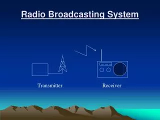
2 Draw a block diagram of a AM receiver and explain its operation
The signal from the antenna is usually very weak. Amplification is, therefore, necessary.
3 Draw a block diagram of a AM superherodyne receiver and explain its operation. • Superhetrodyne receiver is the type used in most modern radio and TV receivers. This receiver was designed by Armstrong
The first stage is a standard RF amplifier. • The next stage is the mixer, which accepts two inputs, the output of the RF amplifier and a steady sine wave from the local oscillator (LO). • The function of the mixer is to mix the AM signal with a sine wave to generate a new set of sum and difference frequencies. It can be shown that the mixer output is an AM signal with a constant carrier frequency regardless of the transmitter frequency. • The next stage is the intermediate-frequency (IF) amplifier, which provides signal amplification at a fixed frequency.
Following the IF amplifier stage is the envelope detector, which extracts the message signal from the intermediate radio frequency signal.
A DC level proportional to the received signal's strength is extracted from the detector stage and fed back to the IF amplifiers and sometimes to the mixer and/or the RF amplifier. This is the Automatic Gain Control (AGC) level, which allows relatively constant receiver output for widely variable received signals. • Output of the detector is amplified by audio amplifiers to drive the speaker.
Frequency Conversion • Mixer performs a frequency translation/conversion process.
Consider a 1000-kHz carrier that has been modulated by a 1-kHz sine wave (AM signal into the mixer), thus producing side frequencies at 999 kHz and 1001 kHz. • Suppose that the LO input is a 1455-kHz sine wave. mixer, being a nonlinear device, will generate the following components: • Frequencies at all of the original inputs: 999 kHz, 1000 kHz, 1001 kHz, and 1455 kHz. • Sum and difference components of all the original inputs: 1455 kHz ±(999 kHz, 1000 kHz, and 1001 kHz). This means outputs at 2454 kHz, 2455 kHz, 2456 kHz, 454 kHz, 455 kHz, and 456 kHz. • Harmonics of all the frequency components listed in 1 and 2 and a dc component.
The IF amplifier has a tuned circuit that only accepts components near 455 kHz, in this case 454 kHz, 455 kHz, and 456 kHz. • Since the mixer maintains the same amplitude proportion that existed with the original AM signal input at 999 kHz, 1000 kHz, and 1001 kHz, the signal now passing through the IF amplifiers is a replica of the original AM signal.
The only difference is that now its carrier frequency is 455 kHz. Its envelope is identical to that of the original AM signal. A frequency conversion or translation has occurred that has translated the carrier from 1000 kHz to 455 kHz • A frequency intermediate to the original carrier and intelligence frequencies-which led to the terminology "intermediate frequency amplifier," or IF amplifier.
Tuned-Circuit Adjustment • Now consider the effect of changing the tuned circuit at the front end of the mixer to accept a station at 1600 kHz. This means a reduction in either its inductance or capacitance (usually the latter) to change its center frequency from 1000 kHz to 1600 kHz. • The capacitance in the local oscillator's tuned circuit is simultaneously reduced so that its frequency of oscillation goes up by 600 kHz.
The mixer's output still contains a component at 455 kHz (among others), as in the previous case when we were tuned to a 1000-kHz station. Of course, the other frequency components at the output of the mixer are not accepted by the frequency selective circuits in the IF amplifiers. • Thus, the key to superheterodyne operation is to make the LO frequency "track" with the circuit or circuits that are tuning the incoming radio signal such that their difference is a constant frequency (the IF).
For a 455-kHz IF frequency, the most common case for broadcast AM receivers, this means the LO should always be at a frequency 455 kHz ABOVE the incoming carrier frequency. • The receiver's "front-end" tuned circuits are usually made to track together by mechanically linking (ganging) the capacitors in these circuits on a common variable rotor assembly.
Image Frequency • Example: Incoming carrier frequency • 1000 kHz, • Local oscillator = 1000+455=1455 kHz • Consider another carrier at 1910 kHz • If this is passed through the same oscillator, will have a 1910- 1455=455 kHz component • Therefore, both carriers will be passed through IF amplifie • RF filter should be designed to eliminate image signals • The frequency difference between a carrier and its image signal is: • RF filter doesn’t have to be selective for adjacent stations, have to be selective for image signals • Therefore,
Example 2 • Question: Determine the image frequency for a standard broadcast band receiver using a 455-kHz IF and tuned to a station at 620 kHz. • The first step is to determine the frequency of the LO • The LO frequency minus the desired station's frequency of 620 kHz should equal the IF of 455 kHz.
Hence, fLO - 620 kHz = 455 kHz fLO = 620 kHz + 455 kHz fLO = 1075 kHz. Now determine what other frequency, when mixedwith 1075 kHz, yields an output component at 455 kHz. X - 1075 kHz = 455 kHz X = 1075 kHz + 455 kHz • Thus, 1530 kHz is the image frequency in this situation.
Automatic Gain Control (AGC) • The AGC help to maintain a constant output voltage level over a wide range of RF input signal levels. • Tuning the receiver would be a nightmare. So as to not miss the weak stations, you would have the volume control (in the non-AGC set) turned way up. As you tune into a strong station, you would probably blow out your speaker while a weak station may not be audible. • The received signal from the tuned station is constantly changing as a result of changing weather and atmospheric conditions. The AGC allows you to listen to a station without adjusting the volume control.
4 Compare AM radio broadcasting with FM Broadcasting • FM radio stations have better quality sound than AM radio stations. Reasons • 1 Noise immunity introduced by the non-linear modulation. • 2 Bandwidth of FM stations are 15kHz, whereas AM stations are only 5kHz. • FM receivers can have aerials (antennas) which are half the wavelength of the transmitted carrier (due to the higher frequency of operation). This allows more signal power to be received than the AM.
FM Radio • The FM band extends from 88 to 108 MHz. • The maximum information frequency fm is specified as 15 kHz. (high fidelity) • The minimum bandwidth is to be at least 200 kHz (0.2 MHz). • Therefore, carrier frequencies are separated by 200 kHz.
5 Explain the operation of the FM Superheterodyne Receiver. • The FM Superheterodyne Receiver has many similarities to that of the AM Superheterodyne receiver. • The only apparent differences are the use of the presence of Limiter-discriminator circuitin place of envelope detector • and • the addition of a de-emphasis network
RF stage, mixer, local oscillator, and IF amplifiers are basically similar to those discussed for AM receivers and do not require further elaboration. • The universally standard IF frequency for FM is 10.7 MHz, as compared to 455 kHz for AM. • A limiter is a circuit whose output is a constant amplitude for all inputs above a critical value. Its function in a FM receiver is to remove any unwanted amplitude variations due to noise.
AGC • In addition to the limiting function also providesAGCaction, since signals from the critical minimum value up to some maximum value provide a constant input level to the detector.
Pre-emphasis and De-emphasis. • Despite the fact that FM has superior noise rejection qualities, noise still interferes with an FM signal. This is particularly true for the high-frequency components in the modulating signal. • These high frequencies can at times be larger in amplitude than the high-frequency content of the modulating signal. This causes a form of frequency distortion that can make the signal unintelligible. • To overcome this problem Most FM system use a technique known as Pre-emphasis and De-emphasis.
At the transmitter the modulating signal is passing through a simple network which amplifies the high frequency component more the low-frequency component. • The simplest form of such circuit is a simple high pass filter.
To return the frequency response to its normal level, a de-emphasis circuit is used at the receiver. • This is a simple low-pass filter • The de-emphasis circuit provides a normal frequency response. • The combined effect of pre-emphasis and de-emphasis is to increase the high-frequency components during the transmission so that they will be stronger and not masked by noise. • This improves the signal-to-noise ratio.
6 Briefly explain the operation of a FM Stereo Broadcasting system • All new FM broadcast receivers are being built with provision for receiving stereo, or two-channel broadcasts. • The left (L) and right (R) channel signals from the program material are combined to form two different signals, one of which is the left-plus-right signal and one of which is the left-minus-right signal
An ordinary mono signal consists of the summation of the two channels, i.e. L + R. • If a signal containing the difference between the left and right channels ( L - R) is transmitted then it is possible to reconstitute the left (L) and right (R) signals. • Adding (L + R) + (L - R) gives2L i.e. left signal and subtracting (L + R) - (L - R) gives 2R, i.e. the right signal.
The (L - R) signal is double-sideband suppressed carrier (DSBSC) modulated about a carrier frequency of 38 kHz, with the LSB in the 23 to 38 kHz slot and the USB in the 38 to 53kHz slot. • The (L + R) signal is placed directly in the 0 to 15 kHz slot, and a pilot carrier at 19 kHz is added to synchronize the demodulator at the receiver.
FM Stereo Receiver • The output from the FM detector is a composite audio signal containing the frequency-multiplexed (L + R) and (L - R) signals and the 19-kHz pilot tone. This composite signal is applied directly to the input of the decoding matrix. • The composite audio signal is also applied to one input of a phase-error detector circuit, which is part of a phase locked loop 38-kHz oscillator.