Download
1 / 96
990 likes | 1.43k Vues
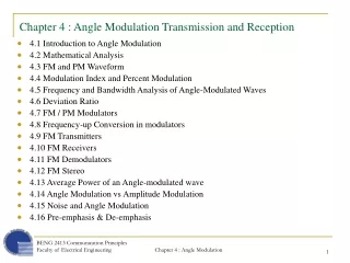
Chapter 3 Analog Signal Transmission and Reception. CONTENTS. Introduction to Modulations Amplitude Modulation Angle Modulation Radio and Television Broadcasting Mobile Radio Systems. 3.1 INTRODUCTION TO MODULATION. Denote m(t) as the analog signal to be transmitted.

E N D
CONTENTS • Introduction to Modulations • Amplitude Modulation • Angle Modulation • Radio and Television Broadcasting • Mobile Radio Systems
3.1 INTRODUCTION TO MODULATION • Denote m(t) as the analog signal to be transmitted. • The signal m(t) is assumed to be a lowpass signal of bandwidth W and is a power-type signal with • The message signal m(t) is transmitted through the communication channel by putting it on a carrier signal of the form carrier amplitude carrier amplitude carrier phase
The signal m(t) modulates the carrier signal c(t) in three forms • Amplitude Modulation (AM) • Frequency Modulation (FM) • Phase Modulation (PM) • Objectives of modulation • Translate the low pass signal m(t) to bandpass signal to match the passband characteristics of the channel. • Accommodate for simultaneous transmission - frequency-division multiplexing (FDM). • Increase the noise immunity in transmission by expanding the bandwidth of the transmitted signal.
3.2 AMPLITUDE MODULATION (AM) • The message signal m(t) is impressed on the amplitude of the carrier signal c(t). • Types of amplitude modulation • Double-sideband, suppressed carruer AM (DSB-SC AM) • Conventional double-sideband AM • Single-sideband AM (SSB AM) • Vestigial-sideband AM (VSB AM)
3.2.1 Double-Sideband Suppressed Carrier AM • A double-sideband, suppressed carrier (DSB-SC) AM signal is obtained by multiplying the message signal m(t) with the carrier signal c(t). • Amplitude modulated signal • The spectrum of the modulated signal can be obtained by taking the Fourier transform of u(t).
upper sideband upper sideband lower sideband
The magnitude of the spectrum of the message signal m(t) has been translated or shifted in frequency by an amount • The phase of the message signal has been translated in frequency and offset by the carrier phase • The bandwidth of the AM signal is 2W, where W is the bandwidth of m(t). • The upper sideband of U(f) contains all the frequency contain of the message signal M(f). • u(t) does not contain carrier components - u(t) is called a suppressed-carrier signal (DSB-SC AM signal)
To compute power content of DSB-SC signal, we first evaluate the time-average autocorrelation function of the signal u(t) • We may show that the following equation equals to zero. Parseval’s relation No frequency overlap
Finally, we have • Taking Fourier transform of both sides • The power spectral density of the DSB-SC signal is the power spectral density of the message shifted upward and downward by and scaled by • The power of the modulated signal where is the power of the message signal
Demodulation of DSB-SC AM Signal • In the absence of noise, and with the assumption of an ideal channel, the received signal can be expressed as • Demodulation of DSB-SC AM signal • Multiply r(t) by a locally generated sinusoid • Pass the product signal through an ideal lowpass filter having a bandwidth W. • Multiplication
The lowpass filter rejects the high frequency components and pass only the low frequency component. Hence, the output of the filter is • Note that m(t) is multiplied by . Thus the desired signal is scaled by a factor that depends on the phase difference between the pahse of the carrier and the phase of the locally generated sinusoid. • If the amplitude of the desired signal is reduced by • If the desired signal component vanishes. • For perfect demodulation, (Phase coherent)
Pilot Tone for Carrier Recovery in DSB AM • Addition a pilot tone to a DSB AM signal- additional power requirement • Carrier recovery by a narrow band filter
3.2.2 Conventional Amplitude Modulation • A conventional AM signal consists of a large carrier component in addition to the double sideband AM modulated signal. The transmitted signal can be expressed as • Advantage: easy to demodulate
It is convenient to express m(t) as where is normalized such that The above equation can be done by using • The scale factor a is called the modulation index. The modulated signal can be expressed as
The spectrum of the amplitude modulated signal u(t) is • The spectrum of a conventional AM signal occupies bandwidth twice the bandwidth of the message signal.
Example: Suppose that the modulating signal is a sinusoid of the form Determine the DSB AM signal, its upper and lower sidebands, and its spectrum, assuming a modulation index of a. Solution: The DSB AM signal
We have already proved in the DSB-SC case, the power in the modulated signal is • For the conventional AM • Finally, we have contains no DC component Message power Carrier power
Advantage of conventional AM signal: easy to be demodulated • Envelope detector
3.2.3 Single-Sideband AM • DSB-SC AM signal requires a channel bandwidth of • The transmission of either sideband is sufficient to reconstruct the message signal m(t) at the receiver. • We may reduce the transmitted bandwidth to W Hz by transmitting only the upper sideband or the lower sideband. • A single sideband AM signal can be represented mathematically as :Hilbert transform of m(t).
Generation of a single-sideband AM signal by Hilbert transform
Generation of a single-sideband AM signal by bandpass filter
Let m(t) be a signal with Fourier transform M(f). • An upper sideband AM signal is obtained by eliminating the lower sideband of a DSB AM signal. • We may pass the DSB AM signal through a highpass filter whose transfer function is given by • Obviously H(f) can be written as
The spectrum of the USSB AM signal is given by • Taking the inverse Fourier transform of both sides, we obtain
For lower sideband (LSSB) AM signal, notice • We have • Finally, we have proved USSB AM LSSB AM
To recover the message signal from SSB AM signal, we require a phase coherent or synchronous demodulator. • First multiply the received signal with the local generated carrier , we have • By passing the above signal through an ideal lowpass filter, we have the output • For perfect demodulation, we must have . desired signal interference
3.2.4 Vestigial-Sideband AM • Relaxing the SSB AM by allowing a part called vestige to appear at the output of the modulator. The resulting signal is called vestigial-sideband (VSB) AM. • Generation of VSB AM • generate a DSB-SC AM signal • pass the DSB-SC AM signal through a sideband filter with frequency response H(f)
In the time-domain the VSB signal may be expressed as : impulse response of the VSB filter • In frequency domain • Consider the demodulation of the VSB signal
We have the product signal • The lowpass filter rejects the double-frequency terms and pass only the components in the frequency range • The signal spectrum at the output of the lowpass filter is • Undistirtion requirement
3.2.5 Implementation of AM Modulator and Demodulator • Power-Law Modulation • Nonliear device • voltage-current characteristic of P-N diode • input is the sum of the message signal and the carrier • Let be the input signal. The output of the nonlinear device can be expressed as
Power-Law AM modulator • Suppose that the nonlinear device is approximated by a second order polynomial.
Input to the nonlinear device • Output of the nonlinear device • The band pass filter with bandwidth 2W centered at yields where by design
Assume that • Let • The diode will turn on if and will turn off if • The output across the load resistor is • Since s(t) is a periodic rectangular function, the Fourier series is
Hence • Passing through a bandpass filter, we have
Ring modulator for DSB-SC AM • If c(t) > 0, 1, 4 on, and 2, 3 off, • If c(t) < 0, 1,4 off, and 2,3 on, 1 2 3 4 C(t)
Therefore, we have • Since c(t) is a periodic function, the Fourier series can be expressed as • The desired DSB-SC AM signal is obtained by passing through a bandpass filter with center frequency and bandwidth 2W.