Chapter 5 Analog Transmission
Chapter 5 Analog Transmission. Black Box. The 4 Data-to-Signal Cases. Data. Black Box. Signal. Analog Data. Analog Signal. Digital Data. Digital Signal. Digital-to-analog Conversion.

Chapter 5 Analog Transmission
E N D
Presentation Transcript
Chapter 5Analog Transmission chap 5
Black Box The 4 Data-to-Signal Cases Data Black Box Signal Analog Data Analog Signal Digital Data Digital Signal chap 5
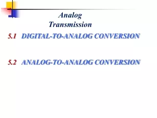
Digital-to-analog Conversion Based on the digital data, the Modulator changes characteristics of the “controllable” analog signal on the transmitter side to represent the digital data Demodulator interprets the analog signal in re-creating the digital data on the receiver side chap 5
More Terminology • Modulation of an analog signal by digital data • The analog signal we can control ? Sine Wave, Carrier Signal, Periodic Signal chap 5
Modulation • ASK, Change amplitude to represent a bit • FSK, Change frequency to represent a bit • PSK, Change phase to represent a bit • QAM, Combination of changing both amplitude and phase to represent a set of bits chap 5
Recall • For digital transmission, bit rate (data rate) and signal rate (baud rate) relationship was S = N x 1/r where r = # of data elements per signal element and N is the data rate in bps (and S is the signaling or baud rate) • For analog, r = log2L where L is the type of signal (versus level) chap 5
Example An analog signal carries 4 bits per signal element. If 1000 signal elements are sent per second, find the bit rate. Solution In this case, r = 4, S = 1000, and N is unknown. We can find the value of N from chap 5
Example An analog signal has a bit rate of 8000 bps and a baud rate of 1000 baud. How many data elements are carried by each signal element? How many signal elements do we need? Solution In this example, S = 1000, N = 8000, and r and L are unknown. We find first the value of r and then the value of L. chap 5
Amplitude Shift Keying B = (1 + d) × S Bandwidth (B) is proportional to the signal rate (S) and depending on the modulation and filtering process, the required bandwidth can range between S to 2S (where middle bandwidth is fc). The value of d relates to the modulation and filtering process chap 5
Example We have an available bandwidth of 100 kHz which spans from 200 to 300 kHz. What are the carrier frequency and the bit rate if we modulated our data by using ASK with d = 1? Solution The middle of the bandwidth is located at 250 kHz. This means that our carrier frequency can be at fc = 250 kHz. We can use the formula for bandwidth to find the bit rate (with d = 1 and r = 1). chap 5
Frequency Shift Keying Use two different carrier frequencies, f1 and f2, for 0 and 1 Changing the original frequency chap 5
Example We have an available bandwidth of 100 kHz which spans from 200 to 300 kHz. What should be the carrier frequency and the bit rate if we modulated our data by using FSK with d = 1? Solution The midpoint of the band is at 250 kHz. We choose 2Δf to be 50 kHz; this means chap 5
Phase Shift Keying changing the original phase not changing the original phase chap 5
QPSK and its implementation QPSK – Quadrature Phase Shift Keying Use 2 bits in each signal element – decreases baud rate and bandwidth Uses 4 possible phases (versus 2) 2 composite signals are created Because the 2 signals are using the same bandwidth – each signal has ½ bandwidth chap 5
Example Find the bandwidth for a signal transmitting at 12 Mbps for QPSK. The value of d = 0. Solution For QPSK, 2 bits is carried by one signal element. This means that r = 2. So the signal rate (baud rate) is S = N × (1/r) = 6 Mbaud. With a value of d = 0, we have B = S = 6 MHz. chap 5
Concept of a constellation diagram Helps define the amplitude and phase of a signal element Peak Amplitude Phase Only use 1 carrier and phase is static and 2 amplitude levels Only use 1 carrier and 1 amplitude and 2 phases (0o and 180o) Uses 2 carriers and 1 amplitude and 4 phases (45o, 135o, -45o, -135o) chap 5
Constellation diagrams for some QAMs QAM – Quadrature Amplitude Modulation For QPSK, we only changed the phase For QAM, we change both the phase and amplitude Has a 0 amplitude and a positive amplitude Has a negative amplitude and a positive amplitude Has 2 positive amplitudes Has 4 negative amplitudes and 4 positive amplitudes chap 5
ANALOG TO ANALOG Analog-to-analog conversion is the representation of analog information by an analog signal. One may ask why we need to modulate an analog signal; it is already analog. Modulation is needed if the medium is bandpass in nature or if only a bandpass channel is available to us. Bandpass – signal being shifted to a particular range Lowpass – signal that IS NOT shifted to a particular range chap 5
Amplitude modulation Vary the amplitude of the carrier signal to mimic the changing voltage levels (amplitude) of the modulating signal result The total bandwidth required for AM can be determined from the bandwidth of the audio signal: BAM = 2B. chap 5
Frequency modulation Vary the frequency of the carrier signal to mimic the changes in voltage level (amplitude) of the modulating signal result The total bandwidth required for FM can be determined from the bandwidth of the audio signal: BFM = 2(1 + β)B. chap 5
Phase modulation Vary the phase of the carrier signal to mimic the changes in voltage level (amplitude) of the modulating signal This illustrates the signal starting at different phases The total bandwidth required for PM can be determined from the bandwidth and maximum amplitude of the modulating signal: BPM = 2(1 + β)B. chap 5