Analog Transmission
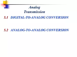
Analog Transmission. DIGITAL-TO-ANALOG CONVERSION. Digital-to-analog conversion is the process of changing one of the characteristics of an analog signal based on the information in digital data. . Topics discussed in this lecture.

Analog Transmission
E N D
Presentation Transcript
DIGITAL-TO-ANALOG CONVERSION Digital-to-analog conversion is the process of changing one of the characteristics of an analog signal based on the information in digital data. Topics discussed in this lecture Aspects of Digital-to-Analog ConversionAmplitude Shift KeyingFrequency Shift Keying Phase Shift Keying Quadrature Amplitude Modulation
Digital-to-analog conversion Digital to analog conversion is the process of changing one of the characteristics of an analog signal based on the information in digital data By changing one of the sine wave characteristic, we can represent digital data
Digital-to-analog conversion • Bit rate is the number of bits per second. Baud rate is the number of signal elements per second. • In the analog transmission of digital data, the baud rate is less than or equal to the bit rate. Example An analog signal carries 4 bits per signal element. If 1000 signal elements are sent per second, find the bit rate. Solution In this case, r = 4, S = 1000, and N is unknown. We can find the value of N from
Digital-to-analog conversion Example An analog signal has a bit rate of 8000 bps and a baud rate of 1000 baud. How many data elements are carried by each signal element? How many signal elements do we need? Solution In this example, S = 1000, N = 8000, and r and L are unknown. We find first the value of r and then the value of L.
Example We have an available bandwidth of 100 kHz which spans from 200 to 300 kHz. What are the carrier frequency and the bit rate if we modulated our data by using ASK with d = 1? Solution The middle of the bandwidth is located at 250 kHz. This means that our carrier frequency can be at fc = 250 kHz. We can use the formula for bandwidth to find the bit rate (with d = 1 and r = 1).
Example In data communications, we normally use full-duplex links with communication in both directions. We need to divide the bandwidth into two with two carrier frequencies. The available bandwidth for each direction is 50 kHz, which leaves us with a data rate of 25 kbps in each direction.
Binary frequency shift keying Example We have an available bandwidth of 100 kHz which spans from 200 to 300 kHz. What should be the carrier frequency and the bit rate if we modulated our data by using FSK with d = 1? Solution The midpoint of the band is at 250 kHz. We choose 2Δf to be 50 kHz; this means
Bandwidth of MFSK Implementation B = L x S
Example We need to send data 3 bits at a time at a bit rate of 3 Mbps. The carrier frequency is 10 MHz. Calculate the number of levels (different frequencies), the baud rate, and the bandwidth. Solution We can have L = 23 = 8. The baud rate is S = 3 MHz/3 = 1000 Mbaud. This means that the carrier frequencies must be 1 MHz apart (2Δf = 1 MHz). The bandwidth is B = 8 × 1000 = 8000.
PSK uses a finite number of phases, each assigned a unique pattern of binary digits. • Each pattern of bits forms the symbol that is represented by the particular phase. There are two fundamental ways of utilizing the phase of a signal in this way: • By viewing the phase itself as conveying the information, in which case the demodulator must have a reference signal to compare the received signal's phase against; (Coherent PSK) • By viewing the change in the phase as conveying information — differential schemes, some of which do not need a reference carrier. (Differential PSK) Binary phase shift keying A convenient way to represent PSK schemes is on a constellation diagram
Represents the possible symbols that may be selected by a given modulation scheme as points in the complex plane. By representing a transmitted symbol as a complex number and modulating a cosine and sine carrier signal with the real and imaginary parts (respectively), the symbol can be sent with two carriers on the same frequency. The real and imaginary axes are often called the in phase, or I-axis and the quadrature, or Q-axis. Concept of a constellation diagram Plotting several symbols in a scatter diagram produces the constellation diagram. The points on a constellation diagram are called constellation points. They are a set of modulation symbols which comprise the modulation alphabet
Constellation diagrams for some QAMs The constellation diagrams for an ASK (OOK), BPSK, and QPSK signals.
The wireless LAN standard, IEEE 802.11b-1999, uses a variety of different PSKs. • 1 Mbit/s differential BPSK • 2 Mbit/s DQPSK • 5.5 Mbit/s and the full-rate of 11 Mbit/s QPSK • Bluetooth 2 • DQPSK at its lower rate (2 Mbit/s) • 8-DPSK at its higher rate (3 Mbit/s) • IEEE 802.15.4 (the wireless standard used by ZigBee) also relies on PSK Application
Uses two phases which are separated by 180° It does not matter exactly where the constellation points are positioned In the presence of an arbitrary phase-shift introduced by the communications channel, the demodulator is unable to tell which constellation point is which. As a result, the data is often differentially encoded prior to modulation. Binary phase shift keying • The general form for BPSK follows the equation: • This yields two phases, 0 and π. • for binary “0” • for binary “1” Tb= Bit duration Eb= Energy per bit Basis function
Binary phase shift keying Implementation of BASK
QPSK uses four points on the constellation diagram, equispaced around a circle. With four phases, QPSK can encode two bits per symbol, shown in the diagram with gray coding to minimize the bit error rate. Quadrature PSK and its implementation • The mathematical analysis shows that QPSK can be used either to double the data rate compared with a BPSK system while maintaining the samebandwidthof the signal, or to maintain the data-rate of BPSK but halving the bandwidth needed. • Writing the symbols in the constellation diagram in terms of the sine • and cosine waves used to transmit them: • This yields the four phases π/4, 3π/4, 5π/4 and 7π/4 as needed. TsSymbol duration, Es Energy-per-symbol = with n bits per symbol
Quadrature PSK and its implementation Quadrature amplitude modulation is a combination of ASK and PSK.
Two-dimensional signal space with unit basis functions The signal constellation consists of the signal-space 4 points Quadrature PSK and its implementation Transmitter Receiver
The odd-numbered bits have been assigned to the in-phase component and the even-numbered bits to the quadrature component QPSK signal in the time domain • Jumps in phase can be seen as the PSK changes the phase on each component at the start of each bit-period.
In differentially-encoded QPSK (DQPSK), the phase-shifts are 0°, 90°, 180°, -90° corresponding to data '00', '01', '11', '10'. This kind of encoding may be demodulated in the same way as for non-differential PSK but the phase ambiguities can be ignored. Differential phase-shift keying (DPSK) • In general, channel introduces an unknown phase-shift to the PSK signal; in these cases the differential schemes can yield a better error-rate than the ordinary schemes which rely on precise phase information
The amplitude of two waves, 90 degrees out-of-phase with each other (in quadrature) are changed to represent the data signal. Amplitude modulating two carriers in quadrature can be equivalently viewed as both amplitude modulating and phase modulating a single carrier. When transmitting two signals by modulating them with QAM, the transmitted signal will be of the form: At the receiver, these two modulating signals can be demodulated using a coherent demodulator. In the ideal case I(t) is demodulated by multiplying the transmitted signal with a cosine signal: Quadrature amplitude modulation Removed by Low-pass filter
If data-rates beyond those offered by 8-PSK are required, it is more usual to move to QAM since it achieves a greater distance between adjacent points in the I-Q plane by distributing the points more evenly. The complicating factor is that the points are no longer all the same amplitude and so the demodulator must now correctly detect both phase and amplitude, rather than just phase. Quantized QAM • Communication systems designed to achieve very high levels of spectral efficiency usually employ very dense QAM constellations
Quantized QAM: Ideal structure Transmitter Receiver
We'll use a signal that is transmitting at 3600 bps, or 3 bits per baud. This means that we can represent 8 binary combinations. We'll use 2 measures of amplitude, 1 and 2, just we did before. We'll also use 4 possible phase shifts. Combining the two, we have 8 possible waves that we can send. Quantized QAM: Example Let's encode a big bit stream: 001010100011101000011110 First, we break it up into 3-bit triads: 001-010-100-011-101-000-011-110
Example Find the bandwidth for a signal transmitting at 12 Mbps for QPSK. The value of d = 0. Solution For QPSK, 2 bits is carried by one signal element. This means that r = 2. So the signal rate (baud rate) is S = N × (1/r) = 6 Mbaud. With a value of d = 0, we have B = (1+d)S=S = 6 MHz.
ANALOG AND DIGITAL Analog-to-analog conversion is the representation of analog information by an analog signal. Why we need to modulate an analog signal; it is already analog? Modulation is needed if the medium is bandpass in nature or if only a bandpass channel is available to us. Amplitude ModulationFrequency ModulationPhase Modulation
Amplitude modulation The total bandwidth required for AM can be determined from the bandwidth of the audio signal: BAM = 2B. AM band allocation
Frequency modulation The total bandwidth required for FM can be determined from the bandwidth of the audio signal: BFM = 2(1 + β)B. FM band allocation
Phase modulation The total bandwidth required for PM can be determined from the bandwidth and maximum amplitude of the modulating signal: BPM = 2(1 + β)B.