Download
1 / 44
470 likes | 576 Vues
This section covers the process of converting digital data into analog signals through techniques like ASK and FSK. Learn about aspects, bandwidth, modulation, and examples related to the conversion process.

E N D
Chapter 5 Analog Transmission
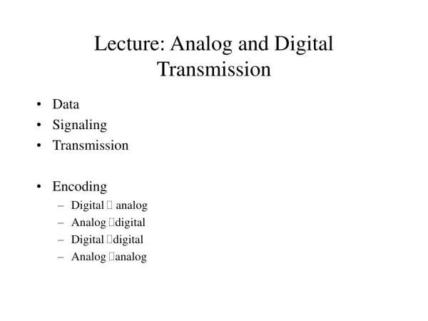
5.1 DIGITAL-TO-ANALOG CONVERSION Digital-to-analogconversion is the process of changing one of the characteristics of an analog signal based on the information in digital data. Topics discussed in this section: Aspects of Digital-to-Analog ConversionAmplitude Shift KeyingFrequency Shift Keying Phase Shift Keying Quadrature Amplitude Modulation
5.1 Digital-to-Analog Conversion Figure 5.1 Digital-to-analog conversion
Digital-to-Analog Conversion (cont’d) • Type of Digital-to-Analog encoding
Digital-to-Analog Conversion • Data Rate Vs Signal rate • Data (bit) rate : the number of bits per second. • Signal (baud) rate : the number of signal elements per second. • S = N x 1/r • where N= data rate (bit per second) • r= log2 L (No. of data elements carried in one signal element) • Bit rate = baud rate x No. of bits represented by each signal element • In the analog transmission of digital data, the Baud rate is less than or equal to the bit rate • Carrier Signal or Carrier Frequency (반송신호 또는 주파수 ) • base signal for the information signal
Digital-to-Analog Conversion (cont’d) Example 5.1 An analog signal carries 4 bits per signal element. If 1000 signal elements are sent per second, find the baud rate and bit rate. Solution In this case, r = 4, S = 1000, and N is unknown. We can find the value of N from • Baud rate = Number of signal elements = 1000 bauds per second
Digital-to-Analog Conversion (cont’d) Example 5.2 An analog signal has a bit rate of 8000 bps and a baud rate of 1000 baud. How many data elements are carried by each signal element? How many signal elements do we need? Solution In this example, S = 1000, N = 8000, and r and L are unknown. We find first the value of r and then the value of L.
Digital-to-Analog Conversion - ASK • ASK(Amplitude Shift Keying) • The amplitude of the carrier signal is varied to create signal element. Both frequency and phase remain constant while the amplitude changes. • Highly susceptible to noise interference Figure 5.3 Binary amplitude shift keying
Digital-to-Analog Conversion - ASK Bandwidth for ASK • Although the carrier signal is only one simple sine wave, the process of modulation produces a nonperiodic composite signal. • Relationship between Signal rate and Bandwidth in ASK • B (Bandwidth) = (1 + d) x S • S : Signal rate (baud) • d : factor related to the modulation and filtering process (value of d is between 1 & 0) = S Maximum Bandwidth = 2S
Digital-to-Analog Conversion - ASK Figure 5.4 Implementation of binary ASK
Digital-to-Analog Conversion - ASK Example 5.3 We have an available bandwidth of 100 kHz which spans from 200 to 300 kHz. What are the carrier frequency and the bit rate if we modulated our data by using ASK with d = 1? Solution The middle of the bandwidth is located at 250 kHz. This means that our carrier frequency can be at fc = 250 kHz. We can use the formula for bandwidth to find the bit rate (with d = 1 and r = 1).
Digital-to-Analog Conversion - ASK Example 5.4 In data communications, we normally use full-duplex links with communication in both directions. We need to divide the bandwidth into two with two carrier frequencies, as shown in Figure 5.5. The figure shows the positions of two carrier frequencies and the bandwidths. The available bandwidth for each direction is now 50 kHz, which leaves us with a data rate of 25 kbps in each direction. Figure 5.5 Bandwidth of full-duplex ASK used in Example 5.4
Digital-to-Analog Conversion - FSK • FSK(Frequency Shift Keying) • the frequency of the carrier signal is varied to represent binary 1 or 0. (Peak amplitude and phase remain constant) Figure 5.6 Binary frequency shift keying • Both f1 & f2 are Δf apart from the midpoint between the two bands. • The difference between the two frequency is 2Δf
Digital-to-Analog Conversion - FSK • Bandwidth for FSK • The carrier signals are only simple sine waves, but the modulation creates a nonperiodic composite signal with continuous frequencies. • FSK as two ASK signals, each with its own carrier frequency (f1 or f2) • BBFSK (Bandwidth) = (1+d) x S + 2Δf = (1+d) x S + 2Δf
Digital-to-Analog Conversion - FSK Example 5.5 We have an available bandwidth of 100 kHz which spans from 200 to 300 kHz. What should be the carrier frequency and the bit rate if we modulated our data by using FSK with d = 1? Solution This problem is similar to Example 5.3, but we are modulating by using FSK. The midpoint of the band is at 250 kHz. We choose 2Δf to be 50 kHz; this means
Digital-to-Analog Conversion - FSK Figure 5.7 Implementation of binary FSK
Digital-to-Analog Conversion - FSK • MFSK : Multilevel FSK • We can send data 2-bits at a time by using 4 frequencies. • BMFSK (Bandwidth) = (1+d) x S + (L-1)2Δf => L x S • The minimum value of 2Δf should be at least S for the proper operation of modulation and demodulation.
Digital-to-Analog Conversion - FSK Example 5.6 We need to send data 3 bits at a time at a bit rate of 3 Mbps. The carrier frequency is 10 MHz. Calculate the number of levels (different frequencies), the baud rate, and the bandwidth. Solution We can have L = 23 = 8. The baud rate is S = 3 MHz/3 = 1 Mbaud. This means that the carrier frequencies must be 1 MHz apart (2Δf = 1 MHz). The bandwidth is B = 8 × 1000 = 8000KHz. Figure 5.8 shows the allocation of frequencies and bandwidth.
Digital-to-Analog Conversion - PSK • PSK • The phase of the carrier is varied to represent two or more different signal elements. • Both peak amplitude and frequency remain constant as the phase changes. Figure 5.9 Binary phase shift keying
Relationship between baud rate and bandwidth in PSK • The bandwidth is the same as that for binary ASK, but less than that for BFSK. +
Digital-to-Analog Conversion - PSK • BPSK (Phase Shift Keying) • the phase is varied to represent binary 1 or 0. phase 0 bit 1 0º 180º 0 1 Constellation diagram
Digital-to-Analog Conversion - PSK Figure 5.10 Implementation of BPSK
QPSK(4-PSK) method • Instead of utilizing only two variations of a signal, We can use 4 variations and let each phase shift represent 2 bits. • This technique is called 4-PSK or Q-PSK.
QPSK(4-PSK) method Figure 5.11 QPSK and its implementation
QPSK(4-PSK) method Example 5.7 Find the bandwidth for a signal transmitting at 12 Mbps for QPSK. The value of d = 0. Solution For QPSK, 2 bits is carried by one signal element. This means that r = 2. So the signal rate (baud rate) is S = N × (1/r) = 6 Mbaud. With a value of d = 0, we have B = S = 6 MHz.
Constellation Diagram Figure 5.12 Concept of a constellation diagram
Constellation Diagram Example 5.8 Show the constellation diagrams for an ASK (OOK), BPSK, and QPSK signals. Solution Figure 5.13 shows the three constellation diagrams.
Digital-to-Analog Conversion - QAM • QAM(Quadrature Amplitude Modulation) • Quadrature amplitude modulation is a combination of ASK and PSK so that a maximum contrast between each signal unit (bit, dibit, tribit, and so on) is achieved Figure 5.14 Constellation diagrams for some QAMs
5.2 ANALOG-TO-ANALOG CONVERSION Analog-to-analog conversion is the representation of analog information by an analog signal. One may ask why we need to modulate an analog signal; it is already analog. Modulation is needed if the medium is bandpass in nature or if only a bandpass channel is available to us. Topics discussed in this section: Amplitude ModulationFrequency ModulationPhase Modulation
Analog-to-analog Conversion • Analog-to-Analog encoding is the representation of analog information by an analog signal. • Analog-to-Analog encoding
Analog-to-Analog Conversion Figure 5.15 Types of analog-to-analog modulation
Analog-to-Analog Conversion - AM • AM(Amplitude Modulation) ~ The frequency and phase of the carrier remain the same; only the amplitude changes to follow variations in the information. Figure 5.16 Amplitude modulation
Analog-to-Analog Conversion - AM • AM bandwidth • The total bandwidth required for AM can be determined from the bandwidth of the audio signal. The total bandwidth required for AM can be determined from the bandwidth of the audio signal: BAM = 2B.
Analog-to-Analog Conversion - AM • AM bandwidth
Analog-to-Analog Conversion - AM • Audio signal(음성과 음악) bandwidth : 5 KHz • Minimum bandwidth : 10 KHz (bandwidth for AM radio station) • AM stations are allowed carrier frequencies anywhere between 530 and 1700 KHz(1.17 MHz) • each frequency must be separated by 10 KHz
Analog-to-Analog Conversion - AM • AM band allocation
Analog-to-Analog Conversion - FM • FM(Frequency Modulation) • as the amplitude of the information signal changes, the frequency of the carrier changes proportionately. Figure 5.18 Frequency modulation
Analog-to-Analog Conversion - FM • FM Bandwidth • The bandwidth of an FM signal is equal to 10 times the bandwidth of the modulating signal. The total bandwidth required for FM can be determined from the bandwidth of the audio signal: BFM = 2(1 + β)B.
Analog-to-Analog Conversion - FM • FM bandwidth
Analog-to-Analog Conversion - FM • Bandwidth of an audio signal broadcast in stereo : 15 KHz • minimum bandwidth : 150 KHz • allows generally 200 KHz(0.2 MHz) for each station • FM station are allowed carrier frequencies anywhere 88 and 108 MHz (each 200 KHz)
Analog-to-Analog Conversion - FM • FM band allocation Alternate bandwidth allocation
Analog-to-Analog Conversion - PM • PM(Phase Modulation) • The phase of the carrier signal is modulated to follow the changing voltage (amplitude) of the modulating signal • ~ is used in some systems as an alternative to frequency modulation. Figure 5.20 Phase modulation
Note Analog-to-Analog Conversion - PM The total bandwidth required for PM can be determined from the bandwidth and maximum amplitude of the modulating signal:BPM = 2(1 + β)B.