Dump Heating temperature (Revision 2, part 2)
250 likes | 282 Vues
Dump Heating temperature (Revision 2, part 2). Ang Lee April 7, 2010. Slide from March 16, 2010. For structural calculation:

Dump Heating temperature (Revision 2, part 2)
E N D
Presentation Transcript
Dump Heating temperature(Revision 2, part 2) Ang Lee April 7, 2010
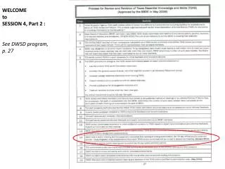
Slide from March 16, 2010 • For structural calculation: • Buckling calculation: to find critical collapsing pressure Pcr for a given structure (E and t) and compare it with CGA (SF=2)or ASME (SF=3) code for the safety factor (SF). Done • Stress calculation : if the structure passes the buckling SF requirement, then the working stress needs to be checked under the operating load (p=15 psi).- done • The thermal stress due to temperature rise. today • The combine stress due to the thermal and structure load (vacuum). today • The deformation if it is required/interested .today
Slide from March 16, 2010Temperature (K) Result after 30 days
ASME SEC VIII, Div 2 ,& SEC II, part D requirement • Pm (primary membrane)< Sm • Pm + Pb(primary bending) < 1.5*Sm • Pm+Pb+Q(secondary stress)< 3*Sm Where the thermal stress is considered to be secondary stress_ Q(self limiting stress) Where Sm is code allowable stress for a given temperature. It is based on Sec II, part D
Stress criteria (ASME) • Seems we need a material with a Sy (min. yield strength= 21 ksi at T=~300F such that Sm (allowable)=2/3*Sy=14 ksi at T=300 F (since Q_secondary stress)<3*Sm=42 ksi By looking on the ASME II, part D table Y
Working &Allowable stress Material 1: C 10200; SB-187 ; copper rod -line19 Sy=6.3 ksi(300F)&5.6 ksi (450F) Then, its allowable Sm=2/3 Sy Sm=4.2 ksi (300 F) & 3.73 ksi (450F) • The stress due to the structure load has to be below the Sm. –> OK. Since max stress due to 15 psi is 1.9 ksi < both 4.2 & 3.72 ksi for given temperature. • Secondary stress due to the thermal loading : Sth<3*Sm = 12.6 & 11.19 ksi Beam section , Sth=27 ksi > 12.6 ksi- not ok. Top plate, Sth=41.5 ksi > 12.6 ksi -> not ok Sided section Sth=36 ksi > 12.6 ksi - not ok 3) If we take a look it more aggressively: Beam section, if we take the “B “ contour and really don’t care that corner section Sth~18 ksi > 12.6 not ok and top plate, if we take “A” contour line, then Sth~14 ksi > 12.6 - not ok again.
Working & Allowable stress • Material 2,C-61400 or C-63000, Table Y , line 21—27, The Yield stress does not change too much as the temperature rise and stays around ~29 to 31 ksi range. Let ‘s take line 25 as an example: Plate or sheet, SB-169, C-61400,temper 025/or 060 Sy=31.1K (300F) & 30.4 ksi (450F) Then its allowable=Sm=30.4*2/3=20.6 ksi (450 F) • The stress due to the structure load has to be below the Sm. –> Yes. Since max stress due to 15 psi is 1.9 ksi<< 20.6ksi for given temperature. 2) Secondary stress due to the thermal loading : Sth<3*Sm = 62 ksi Beam section , Sth=27 ksi < 62 ksi- ok! Top plate, Sth=41.5 ksi <62 ksi -> ok! Sided section Sth=36 ksi < 62 ksi - ok! • So, Material from line 21—27 will work for 100% contact case (most likely case) And also works for 50% contact case where the contact occurs only both end and the beam hits in the center portion-very close to ~0% contact case (most pessimistic case.
Conclusion • Six sided section needs to be a copper with Sy (min) = ~30 ksi at T=450 F due to thermal stress.
Implication for upstream 8”beam Pipe • Since the 8” beam pipe is fixed at the upstream side, the thermal expansion due to the sided section will create a compressive force on that beam pipe besides 15 psi external pressure. We need to take a look
Implication for upstream 8”beam Pipe • First mode will be most unlikely and second mode SF=11 should be sufficient. • The beam pipe will be fine.
Temperature vs time for a given power (100% contact) _additional Thermal W_0-10KW with DW=0.2KW)
Additional Thermal calculationW=0-10 KW with DW=0.2 KW • This temperature vs the beam power curve is the maximum temperature after the “ curve flat” __steady state.
Appendix A _ Thermal stress for the beam section _50% contact case
Appendix A _ Thermal stress for the Top plate_50% contact case
Appendix A _ Thermal stress for the sided section_50% contact case