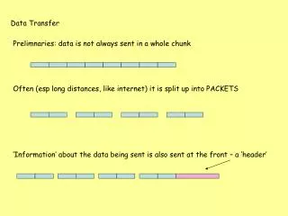
Communication, data transfer
Learn about baseband signals and line coding in communication and data transfer. Explore different encoding techniques, signal modulation, error correction, and clock recovery. Understand the various transmission media and communication directions.

Communication, data transfer
E N D
Presentation Transcript
Communication,data transfer 2. Baseband signals, line coding 2018. 04. 14.
Categorization • Medium • Coding • Modulation • Number of symbols (size of alphabet) • Spectral efficiency • SNR, error correction, clock recovery, etc.
Medium • Wire • ”simple” copper wire • coaxial cable • wave guide • optical fibre • Free space propagation (EM waves) • radio frequency • optical
Number of symbols • Binary: two symbols (0;1) • Non-binary: Sometimes binary coding using more than two levels (eg. AMI, MLT-3).
Number of symbols • Baseband signal is usually binary amplitude modulated (also called ASK, amplitude shift keying, or OOK, on-off keying) • Non binary transfer is usually used in high frequency modulated signals, eg. QPSK / nPSK, QAM, nFSK • eg. digital TV, where high speed is more important than bit errors
Number of symbols • Greater M advantage: greater bit rate per unit bandwidth • Greater M disadvantage: more sensitive to noise/interference, because smaller difference between levels • With given max level (eg. voltage), binary is the most noise tolerant
Direction of communication • Simplex: fixed one way Broadcast (radio, TV), global positioning satellites • Half duplex: one way at a time Eg. PMR, walkie-talkie, amateur radio, I2C, USB • Duplex (full duplex): two way Eg. telephone, RS232, SPI How to create full duplex: • Two (pairs of) wires • Time Division Multiplexing, TDM (eg. telephone) • Frequency Division Multiplexing, FDM (eg. radio) • Code Division Multiplexing, CDM (eg. UMTS)
Participants • Point to point • Master-Slave (SPI) or equal (telephone) • Point to multipoint • One Master, many Slaves (eg. broadcast) • Multipoint to point • One Master, many Slaves (eg. data acquisition) • Multipoint to multipoint • many master, many slave or equals, or changes in time (eg. computer network)
Time/spectral domain • Basic knowledge of spectrum, Fourier-transformation, etc. required • Baseband signal: the original information presented in a simple way, in the spectrum it occupies the part close to zero freq., its bandwidth is proportional to the data rate. • Eg. in analog, the signal from a microphone would be baseband. • Eg. in digital, a square waveform (where impulses represent bits) would be baseband. Such as found in microproc. systems.
Time/spectral domain • Baseband signal
Time/spectral domain • Transposed signal, modulated signal: the baseband signal (modulating signal) is mixed (multiplied) by a high frequency sine wave (carrier), effectively moves the bandwidth to be „around” the carrier; useful for radio or optical comm., for frequency multiplexing.
Time/spectral domain • Modulated signal
Time/spectral domain Baseband Transposed
Baseband coding • Probably the most basic waveform is the binary NRZ square wave (eg. low:0V, high:5V). This is what usually comes out of digital circuits. This is often what we mean by baseband signal inthis topic. This can be re-coded to other coding types (RZ, Manchester, etc.), while still remaining baseband; and can also be transposed to higher frequencies.
Spectrum of square wave • Ideal, infitine periodic square wave... • in real life: • there is limited bandwidth waveform distorted • not infinite; not totally periodic (info content) spectrum modified
Spectrum of square wave • If signal is unipolar, or bipolar with non equal number of 0 and 1, then a DC component will be present (at f=0 in spectrum) • A lack of DC component can be advantageous: • Can be transmitted through capacitive or inductive coupling (eg. transformer) • When mixing up, leaves a small area around the carrier free (eg. for "pilot", carrier signal) • A separate DC component can be included (and separated before the receiver) for power supply
Voltage levels • Asymmetric voltage levels (unipolar) • Symmetric voltage levels (bipolar) • can provide supply voltage if two-way rectified, with limited current usually
...or current levels „Current loop”, most often used variation: • logical 0: 4mA • logical 1: 20mA • open circuit: 0mA • useful for long distance (compensates for voltage drop), detects open circuit • also provides supply current • analog version also exists (4..20mA)
Timing Receiver needs to know when to sample the incoming signal. This is controlled by the data transfer clock. (This is not the same as the processor clock). • Asynchronous • Receiver has own oscillator, needs to be setup in advance or auto config. • Oscillator needs to be fine tuned to incoming signal (no two independent osc. have exactly same freq.!) -> Clock recovery • Synchronous • Clock signal is sent on a separate wire. No separate data clock oscillator is needed in slave (it can have its own processor clock of course). Used for high freq. transmissions.
Clock recovery • With NRZ and similar codes, if too many bits of same value follow, synchron can be lost, because the clock recovery circuit synchronizes on the edges of the incoming signal. • Bit stuffing: after n same bits, an opposite is inserted (this will automatically removed on the output of the receiver). Eg. USB (NRZ-Space) n=6; CAN (NRZ) n=5 • There exist more complex versions of this (eg. Bipolar with 8 zeros substitution) • RZ, Manchester: there is an edge in each bit
Clock recovery: 4B5B • Re-codes 4b symbols to 5b, so to maximize number of edges • Unused 5b symbols can indicate errors • 2x5b control signals also exist (FDDI,Ethernet)
Baseband coding • NRZ Non return to zero • Will have a DC level (because 0/1 ratio is not uniform) • harder to synchronise (when too many bits of same level follow) • eg. RS-232, CAN • Differential versions: • NRZ-Space • 0: change, 1: don’t change • NRZ-Mark or NRZ-Inverted • 0: don’t change, 1: change • (mark=1, space=0 from old telegraph jargon)
Baseband coding • RZ (Return to zero) • Twice bandwidth than NRZ (at same bitrate). • There is an edge in every bit (at least if bipolar), making for easier clock recovery.
Baseband coding • Alternate Mark Inversion (bipolar) 0: 0 level 1: + or – level alternating if two consecutive 1’s are of same level -> error
Baseband coding • MLT-3 (Multi-Level Transmit) 0: same as previous level 1: alternates -; 0; +; 0 levels Smaller bandwidth (eg. 11111111 results in bw ¼ of base harmonic ) Eg. 100BASE-TX Fast Ethernet (LAN) together with 4B5B coding
Baseband coding • Manchester-code Eg. Ethernet, RFID Twice bandwidth, no DC content, easy clock recovery
Baseband coding • Differential Manchester / Biphase Mark Code /FM1 0: change at start of bit, 1: change at end of bit Polarity independent (as all diff.codes) 802.5 Token ring LAN, magnetic and optical storage, AES3,S/PDIF
Code division multiplexing /Spread spectrum modulation /Pulse compression • We can transmit several users’ stream at the same timeslot and same frequency, but in longer time. • Special coding allows to select needed signal from the sum of several signals+noise, if the proper filter function is known. • Also can work as encryption.
Each bit is replaced by a bit sequence. • Receiver is a digital filter, which is practically the sequence itself. • Incoming signal is correlated with this filter. • If the signal is what we look for, we get the autocorrelation function, otherwise a cross-correlation.
The code (sequence) is chosen so that the „sidelobes” of the autocorrelation function and the maxima of the cross correlations are minimal. The „main lobe” is proportional to the code length. • If the received signal matches the filter, we get a high level pulse, otherwise a noise-like waveform.
Code division multiplexing /Spread spectrum modulation /Pulse compression • Example: Barker-3 seq.: +1 +1 -1 • Autocorrelation fnc calc.:
Code division multiplexing /Spread spectrum modulation /Pulse compression • Barker-7 autocorrelation fnc.: Tb: original bit time n=7 long sequence is 7Tb longm. After correlation filter, the waveform is 14Tb long, but the main lobe (impulse) is only 1Tb wide.
Code division multiplexing /Spread spectrum modulation /Pulse compression • DSSS: Direct Sequence Spread Spectrum • CDMA: Code Division Multiple Access: eg. mobile phone systems • Pulse Compression eg. in radar systems