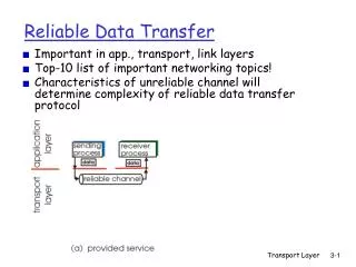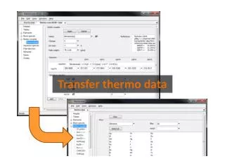
Data Transfer
Data Transfer. From: TCP/IP 網路管理 Craig Hunt 著 第二章 資料傳遞. Reference Book: Computer Networking: A Top Down Approach. 4th edition. Jim Kurose, Keith Ross. Addison-Wesley, July 2007. Outlines. 傳輸的方式. IP addressing Determine the path Address resolution Protocol, port and socket.

Data Transfer
E N D
Presentation Transcript
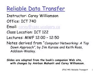
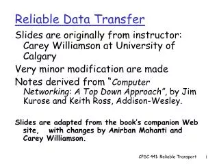
Data Transfer From: TCP/IP 網路管理 Craig Hunt 著 第二章 資料傳遞 Reference Book: Computer Networking: A Top Down Approach. 4th edition. Jim Kurose, Keith Ross. Addison-Wesley, July 2007.
Outlines 傳輸的方式 • IPaddressing • Determine the path • Address resolution • Protocol, port and socket • 以唯一的 IP 位址 決定傳送路徑。 • 封裝與傳送 IP 資料段。 • 利用header中的協定號碼決定是那一個協定。 • 將萃取資料送給此傳輸層協定模組。 • 傳輸層協定以port 號碼決定資料屬於那一個應用行程。
Part 1IP Addressing -- 以唯一的 IP 位址決定傳送路徑
IP Addressing • Provide Internet addressing • Logic addresses • Give each network interface a unique IP address. • Deliver data to the correct host through heterogeneous physical networks
IP Addressing • IPaddress is a 32-bitbinary number: network address + host address • IP address identifies a specific network, and a host in that network. • The prefix length defines the size of network address. • IP address class • Classless Inter-domain Routing(CIDR) and CIDR addressing mask
Principles of IP Addresses • IP address is not assigned to a host. • IP address is assigned to the interface card between the host and network. • If a host has several network interfaces (ex: routers), each interface card needs one IP address.
IP Address Class In the first byte, A: 0 127 B: 128191 C: 192223 D: 224 239 E: 240255
Three Types of IP Addresses • Unicast address • Ex:140.138.136.254 • Multicast address • Ex:224.0.0.9 • First decimal number is 224 through 239 • Broadcast address • Ex:140.138.137.255 • Bits in Host address are all 1s.
Address Space for Each Class • IP address class is not fit the requirement of each organization on Internet.
host part network part 10001100 1000101000010001 00000011 140.138.17.3/11 Classless Inter-domain Routing (CIDR) • Using addressing mask to determine the network space • Network mask is a 32-bit stream • Prefix is all 1s: network part • Suffix is all 0s: host part • Example:mask=255.255.254.0 • 11111111,11111111,11111110,00000000 network address: 140.138.16.0
IP address and Network Mask • You have to set the computer A • IP address (ex: 140.138.137.201) • Network mask (ex: 255.255.254.0) • Default gateway (ex:140.138.136.202) 140.138.137.201=10001100 10001010 1000100111001001 255.255.254.0 =11111111 11111111 1111111000000000 140.138.136.0 =10001100 10001010 1000100000000000 A A and B has the same network address: in the same LAN 140.138.137.202=10001100 10001010 1000100111001010255.255.254.0 =11111111 11111111 1111111000000000 140.138.136.0 =10001100 10001010 10001000 00000000 B A and C don’t have the same network address: in different LAN 140.138.135.108=10001100 10001010 1000011101101100 255.255.254.0 =11111111 11111111 11111110 00000000140.138.134.0 =10001100 10001010 1000011000000000 C
Cost of CIDR • Modify all routing protocolsand routers • Send the network mask except for original IP datagram • IP=192.168.16.122/21 • “/21”denotes that maskhas 211s in prefix
Special IP Addresses • Default route: 0.0.0.0 • Used during bootstrap • Loopback address: 127.0.0.1 • For testing • For all network • Host address is all 0s: the network itself • Host address is all 1s: all hosts in this specified network (called as Directed Broadcast Address) • Limited Broadcast Address: 255.255.255.255 • Broadcast on local network
Private Network • The following addresses are reserved for the private network: • Class A:10.0.0.* • Class B:172.16.*.* to 172.31.*.* • Class C:192.68.0.* to 192.68.255.*
Subnet • For the reason of management, we separate a large network into several subnets. • We set network masks to cut a space of IP addressinto subset. • The number of IP addresses will decrease after cutting. • Subsets may use different physical networks and be connected by routers.
00000000.0000000000001111.1111111100010000.0000000000011111.1111111100100000.0000000000101111.1111111100000000.0000000000001111.1111111100010000.0000000000011111.1111111100100000.0000000000101111.11111111 11110000.0000000011111111.11111111 net 1 net 2 net 3 : net 16 Subnet Example • A large network:172.16.0.0/16 • 172.16.0.1~172.16.255.254 • Network mask: 255.255.0.0 • Separate to 16 subnets • Network mask: 255.255.240.0 • Subnet 1:172.16.0.0/20 • 172.16.0.1~172.16.15.254 • Subnet 2:172.16.16.0/20 • 172.16.16.1~172.16.31.254 • Subnet 3:172.16.32.0/20 • 172.16.32.1~172.16.47.254
Part 2Determine the Path -- 以唯一的 IP 位址決定傳送路徑
Host C1 Host A1 application application Router G1 Router G2 transport transport network network network network data link data link data link data link Network C Network A Network B Logical View of Routing
IP Datagram Routing(1/2) • For all network devicesincluding hosts and gateways, they must decide the paththemselves while sending a datagram to a destination. • If the destination is in the same network, send the datagram to the destination directly. • If the destination is notin the same network, send the datagram to the gateway. • For hosts, to choose a path is just to choose a network.
IP Datagram Routing(2/2) • IP module calculates the network addressof destination IPby using network mask. • Compare with its network address • Not the same:check routing table and find thenext hop. In other words, the IP address of gateway which would forward this datagram. • This device uses ARPto get the MAC address of destination or gateway and put it on the Ethernetframe. • IP datagram is encapsulated into Ethernet frame without modification.
IP Encapsulation • IP datagram is enveloped inEthernet frame. • The destination MAC address in Ethernet frame points to next hop in the delivering path.
peanut walnut 172.16.12.2 172.16.12.4 08:00:20:00:0e:c8 00:c0:34:17:b2:20 Ethernet 00:20:af:1e:7e:5e 08:00:20:22:fd:50 172.16.12.3 172.16.12.1 pecan almond 172.16.1.5 10.104.0.19 banana 04:39:0f:15:34:f0 08:20:8a:6d:e4:38 172.16.1.0 token-ring 172.16.1.2 Internet 03:70:5b:11:34:50 Peanut Network 172.16.12.0/24
Peanut Example • network mask:255.255.255.0 • Peanut has network prefix:172.16.12.0 • Case1: Source=peanut, Destination=walnut • 255.255.255.0 & 172.16.12.4 = 172.16.12.0 • Next hop = 172.16.12.4 • Case2: Source=peanut, Destination=banana • 255.255.255.0 & 172.16.1.2 = 172.16.1.0 • Next hop = 172.16.12.3
Source peanut Destination banana Gateway pecan application application transport transport destination gateway destination gateway destination gateway 172.16.1.0 172.16.12.3 172.16.1.0 172.16.12.5 172.16.1.0 172.16.1.2 172.16.12.0 172.16.12.2 172.16.12.0 172.16.12.3 Default 172.16.1.5 Default 172.16.12.1 Default 172.16.12.1 network access 172.16.12.2 network access 172.16.12.3 172.16.1.5 network access 172.16.1.2 IP module in peanut network
Addresses in Routing Path • peanut walnut • peanut pecan banana Source: IP:172.16.12.2 MAC:08:00:20:00:0e:c8 Destination: IP:172.16.12.4 MAC:00:c0:34:17:b2:20 Source: IP:172.16.12.2 MAC:08:00:20:00:0e:c8 Destination: IP:172.16.1.2 MAC:00:20:af:1e:7e:5e Source: IP:172.16.12.2 MAC:04:39:0f:15:34:f0 Destination: IP:172.16.1.2 MAC:03:70:5b:11:34:50
Routing Table • 儲存到某一目的地主機(destination)封包傳送的路徑。 • Routing table 可能是由 System manager 提供或由 Routing protocol 建立。 • Example:Peanut Routing Table • UNIX以 netstat -nr 顯示路由表
Peanut Routing Table • Destination Gateway Flags Ref Use Interface • 127.0.0.1 127.0.0.1 UH 1 298 lo0 • default 172.16.12.1 UG 2 50360 • 172.16.12.0 172.16.12.2 U 40 111379 le0 • 172.16.2.0 172.16.12.3 UG 4 1179 • 172.16.1.0 172.16.12.3 UG 10 1113 • 172.16.3.0 172.16.12.3 UG 2 1379 • 172.16.4.0 172.16.12.3 UG 4 1119
netstat -nr (mis) • mis:~$ netstat -r Kernel IP routing table Destination Gateway Genmask Flags MSS Window irtt Iface localnet * 255.255.255.0 U 0 0 0 eth0 loopback * 255.0.0.0 U 0 0 0 lo default 140.126.155.254 0.0.0.0 UG 0 0 0 eth0 • mis:~$ netstat -nr Kernel IP routing table Destination Gateway Genmask Flags MSS Window irtt Iface 140.126.155.0 0.0.0.0 255.255.255.0 U 0 0 0 eth0 127.0.0.0 0.0.0.0 255.0.0.0 U 0 0 0 lo 0.0.0.0 140.126.155.254 0.0.0.0 UG 0 0 0 eth0
netstat -nr (ms) • Destination Gateway Flags Refs Use Netif Expire • default 140.126.111.20 UGSc 48 1531 fxp0 • 127.0.0.1 127.0.0.1 UH 1 54 lo0 • 140.126.111/24 link#1 UC 0 0 fxp0 • 140.126.111.1 0:90:27:76:a2:62 UHLW 1 1863 fxp0 1182 • 140.126.111.3 0:a0:c9:8b:61:e3 UHLW 1 157 lo0 • 140.126.111.4 0:80:c8:ef:7c:69 UHLW 0 178 fxp0 961 • 140.126.111.19 link#1 UHLW 2 0 fxp0 • 140.126.111.20 0:e0:63:3:df:80 UHLW 48 0 fxp0 1197 • 140.126.111.153 0:80:c8:ef:46:5d UHLW 1 336 fxp0 683 • 140.126.111.155 0:80:c8:ef:7f:f4 UHLW 0 223 fxp0 1012 • 140.126.111.157 0:c0:26:ef:6:53 UHLW 1 2716 fxp0 618 • 140.126.111.162 0:80:c8:ef:46:62 UHLW 0 27 fxp0 1178 • 140.126.111.255 ff:ff:ff:ff:ff:ff UHLWb 1 3023 fxp0 • 140.126.161.23 140.126.111.19 UGHD 0 3 fxp0 • 140.126.161.31 140.126.111.19 UGHD 0 419 fxp0
netstat -in (ms) $ netstat -in Name Mtu Network Address Ipkts Ierrs Opkts Oerrs Coll fxp0 1500 <Link> 00.a0.c9.8b.61.e3 2060401 1 2036174 0 0 fxp0 1500 140.126.111/2 140.126.111.3 2060401 1 2036174 0 0 lp0* 1500 <Link> 0 0 0 0 0 tun0* 1500 <Link> 0 0 0 0 0 sl0* 552 <Link> 0 0 0 0 0 ppp0* 1500 <Link> 0 0 0 0 0 lo0 16384 <Link> 361 0 361 0 0 lo0 16384 127 127.0.0.1 361 0 361 0 0
ifconfig for Checking Interface $ ifconfig fxp0 fxp0: flags=8843<UP,BROADCAST,RUNNING,SIMPLEX,MULTICAST> mtu 1500 inet 140.126.111.3 netmask 0xffffff00 broadcast 140.126.111.255 ether 00:a0:c9:8b:61:e3 media: autoselect (100baseTX <full-duplex>) status: active supported media: autoselect 100baseTX <full-duplex> 100baseTX 10baseT/UP $ ifconfig lp0 lp0: flags=8810<POINTOPOINT,SIMPLEX,MULTICAST> mtu 1500 • Note: “winipcfg” used in Windows “ipconfig” used in MSDOS
Part 3Address Resolution -- 封裝與傳送 IP 資料段 (1/2)
Binding Protocol Addresses • Protocol addresses (or logical addresses) are abstractions provided by software in the upper layer. • Example:IP address is protocol address • Physical network hardware does not know how to locate the next hop from its protocol address. • The Protocol address of the next hop must be translated to its hardware address (or physical address) before a packet is sent.
Address Resolution • A host or router uses address resolution when it needs to send a packet to another computer on the same physical network. • Mapping between a protocol address and a hardware address is called address resolution.
Address Resolution and Binding Address IP Addresses for TCP/IP MAC Addresses for Ethernet
Address Resolution Protocol(ARP) • Network Access Layer calls ARP and translate IP address intoEthernet MAC. • ARP software creates an address resolution table. • Whenever ARP software receives a translation request, it checks the table. • Exist:reply the Ethernet address • Not exist:ARP broadcasts a query with an IP. Then the host owned thisIP will reply its MAC address. ARP will save the information into the table.
Address Resolution Table • Display and modify the IP-to-Physical address translation tables used by address resolution protocol (ARP) • % arp peanut peanut (172.16.12.2) at 8:0:20:0:e:c8 • Refer to ARP.ppt
arp for peanut network Net to Media Table Device IP Address Mask Flags Phys Addr ------- ---------------------------- ---------------------- ------ ---------------------- le0 peanut.nuts.com 255.255.255.255 08:00:20:00:0e:c8 le0 acorn.nuts.com 255.255.255.255 08:00:02:05:21:33 le0 almond.nuts.com 255.255.255.255 SP 08:00:20:22:fd:51 le0 pecan.nuts.com 255.255.255.255 00:20:af:1e:7e:5f le0 base-address.mcast.net 240.0.0.0 SM 01:00:5e:00:00:00
Part 4Encapsulation -- 封裝與傳送 IP 資料段 (2/2)
IP Encapsulation • For delivery of IP datagram on physical networks, IP datagram must be encapsulated in aframe. • Different physical networks can deliver frames with different size. • IP module need to perform the fragmentationand reassembly of IP datagrams whenever the frame size of the next physical network is smaller than the one of current physical network.
Maximum Transmission Unit (MTU) • Network links have MTU - largest possible link-level frame. • Different link types, different MTUs • Example:FDDI 4352 bytes、Ethernet 1500 bytes、x.25 576 bytes、PPP 296 bytes • Large IP datagram divided • Fragment one datagram to several datagrams • “Reassembled” only at final destination • IP header bits used to identify, order related fragments
Sending Data on Internet MTU= 5000 MTU= 1500 MTU= 800
Fragment and ReassembleIP Datagram • How to reassemble fragments: • Sender gives a unique IDENTIFICATION and saves it in the IP header. Whenever routers separate an original IP datagram, routers copy IDENTIFICATION to all new IP datagrams(called as fragment.) • Receiver uses IDENTIFICATION and source IP addressto resemble the original datagram。In addition, by using FRAGMENT OFFSET, the data is combined together with correct order。
1420 network 3 MTU= 800 14567 1 000 Fragment 1 820 14567 1 175 network 1 MTU= 5000 Bytes 0000-1399 Fragment 2 4020 1420 Bytes 1400-2199 14567 0 000 14567 1 175 Fragment 2.1 620 Bytes 0000-3999 Bytes 1400-2799 14567 1 275 Original Datagram 1220 14567 0 350 network 2 MTU= 1500 Bytes 2200-2799 Fragment 2.2 Fragment 3 Bytes 2800-3999 Detailed Fragmentation Example Note: length = length of (data+ header )
Part 5Protocol Number -- 利用 header 中的 protocol 號碼 決定是那一個傳輸層協定
TCP/IP Layers Port numbers Protocol numbers
Multiplexing • Network system collects data from many APs, puts them into sometransport layer protocols, and then combined all into an IP datagram. • It is called as multiplexing. • On the contrary, the data in IPdatagram must be de-multiplexed to APs. • IP module use protocol numberto indicate the upper transport layer. • Transport layer uses port numberto indicate the upper AP.