PLC System Selection, Installation & Maintenance Guide
This comprehensive guide covers the selection process, installation techniques, maintenance methods, and troubleshooting steps for Programmable Logic Controllers (PLC) used in automation systems. Learn about capacity, memory size, software language, system expansion, support, backup, and more.

PLC System Selection, Installation & Maintenance Guide
E N D
Presentation Transcript
Objective : • PLC selection procedure • Define capacity input/output • Define types input/output • Define memory size • Describe types of software language • Describe future system expansion • Describe support and backup • Installation Technique • Define site installation condition consideration • Define panel/cabinet installation consideration • Define precautions for wiring • Define techniques to solve instable voltage and voltage spike problems • PLC maintenance and troubleshooting methods • PLC external fault • PLC internal fault • Methods to modify programs • Programming and monitoring methods • Preventive maintenance methods • Steps for troubleshooting PLC system UNIT 6SELECTING, INSTALLING, MAINTENANCE AND TROUBLESHOOTING PLC SYSTEM
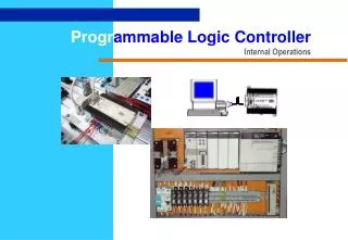
UNIT 6SELECTING, INSTALLING, MAINTENANCE AND TROUBLESHOOTING PLC SYSTEM PLC Selection Procedure INTRODUCTION After the planning phase of the design, the equipment can be ordered. This decision is usually based upon the required inputs, outputs and functions of the controller. The first decision is the type of controller; rack, mini, micro, or software based. This decision will depend upon the basic criteria listed below. • Number of logical inputs and outputs. • Memory - Often 1K and up. Need is dictated by size of ladder logic program. A ladder element will take only a few bytes, and will be specified in manufacturers documentation. • Number of special I/O modules - When doing some exotic applications, a large number of special add-on cards may be required. • Scan Time - Big programs or faster processes will require shorter scan times. And, the shorter the scan time, the higher the cost. Typical values for this are 1 microsecond per simple ladder instruction • Communications - Serial and networked connections allow the PLC to be programmed and talk to other PLCs. The needs are determined by the application. • Software - Availability of programming software and other tools determines the programming and debugging ease.
UNIT 6SELECTING, INSTALLING, MAINTENANCE AND TROUBLESHOOTING PLC SYSTEM PLC Selection Procedure • The process of selecting a PLC can be broken into the steps listed below. • 1. Understand the process to be controlled (Note: This is done using the design sheets in the previous chapter). • List the number and types of inputs and outputs. • • Determine how the process is to be controlled. • Determine special needs such as distance between parts of the process. • 2. If not already specified, a single vendor should be selected. Factors that might be considered are : • • Manuals and documentation • • Support while developing programs • • The range of products available • Support while troubleshooting • • Shipping times for emergency replacements • • Training • • The track record for the company • Business practices (billing, upgrades/obsolete products, etc.) • 3. Plan the ladder logic for the controls. • 4. Count the program instructions and enter the values into the sheets. Use the instruction times and memory requirements for each instruction to determine if the PLC has sufficient memory, and if the response time will be adequate for the process.
UNIT 6SELECTING, INSTALLING, MAINTENANCE AND TROUBLESHOOTING PLC SYSTEM PLC Selection Procedure
UNIT 6SELECTING, INSTALLING, MAINTENANCE AND TROUBLESHOOTING PLC SYSTEM PLC Selection Procedure The I/O Unit has two type; Discrete I/O and Analog I/O. Digital I/O modules have digital I/O circuits that interface to on/off sensors such as push-button and limit switches and on/off actuators such as motor starters, pilot lights, and annunciators. Analog I/O modules perform the required A/D and D/A conversions using up to 16-bit resolution. Analog I/O can be user-configured for the desired faultresponse state in the event that I/O communication is disrupted. This feature provides a safe reaction/response in case of a fault, limits the extent of faults, and provides a predictable fault response. Digital I/O modules cover electrical ranges from 5 to 276 V AC or DC, and relay contact output modules are available for ranges from 0 to 276 V AC or 0 to 175 V DC. A range of analog signal levels can be accommodated, including standard analog inputs and outputs and direct thermocouple and RTD temperature inputs.
UNIT 6SELECTING, INSTALLING, MAINTENANCE AND TROUBLESHOOTING PLC SYSTEM PLC Selection Procedure • Programmers • There are a few basic types of programmers in use. These tend to fall into 3 categories ; • PLC Software for Personal Computers - Similar to the specialized programming units, but the software runs on a multi-use, user supplied computer. This approach is typically preferred. • 2. Hand held units (or integrated) - Allow programming of PLC using a calculator type interface. Often done using mnemonics. • 3. Specialized programming units - Effectively a portable computer that allows graphical editing of the ladder logic, and fast uploading/downloading/monitoring of the PLC
UNIT 6SELECTING, INSTALLING, MAINTENANCE AND TROUBLESHOOTING PLC SYSTEM PLC Installation • Panel/Cabinet Installation • Consider PLC operation, maintenance, and surrounding conditions when installing the PLC in a panel or cabinet. The operating temperature range for the PLC is 0°C to 55°C. Be sure that there is adequate ventilation for cooling; • Allow enough space for air circulation. • Do not install the PLC above equipment that generates a large amount of heat, such as heaters, transformers, or large resistors. • Install a cooling fan or system when the ambient temperature exceeds 55°C • See the picture below; The small PLC in panel The big PLC in panel
UNIT 6SELECTING, INSTALLING, MAINTENANCE AND TROUBLESHOOTING PLC SYSTEM PLC Installation • Power lines & high-voltage equipment can cause electrical noise in the PLC ; • Do not install the PLC in a panel or cabinet with high-voltage equipment • Allow at least 200 mm between the PLC and nearby power lines • See the picture below; • Ensure that the PLC can be accessed for normal operation and maintenance; • Provide a clear path to the PLC for operation and maintenance. High-voltage equipment or power lines could be dangerous if they are in the way during routine operations. • The PLC will be easiest to access if the panel or cabinet is installed about 3 to 5 feet above the floor
UNIT 6SELECTING, INSTALLING, MAINTENANCE AND TROUBLESHOOTING PLC SYSTEM PLC Installation 2. Installing the CPU Unit & I/O Unit The small PLC must be installed in the position shown below to ensure adequate cooling. See the picture below; Do not install the small PLC in either of the following positions.
UNIT 6SELECTING, INSTALLING, MAINTENANCE AND TROUBLESHOOTING PLC SYSTEM PLC Installation The small PLC can be installed on a horizontal surface or on a DIN track. See the picture below ; Lower the small PLC so that the notch on the back of the PLC catches the top of the DIN Track. Push the PC forward until the lock snaps into place. See the picture below ;
UNIT 6SELECTING, INSTALLING, MAINTENANCE AND TROUBLESHOOTING PLC SYSTEM PLC Installation The Backplane is a simple device having two functions. The first is to provide physical support for the Units to be mounted to it. The second is to provide the connectors and electrical pathways necessary for connecting the Units mounted to it. The core of the PLC is the CPU. The CPU contains the program consisting of the series of steps necessary for the control task. The CPU has a built-in power supply, and fits into the rightmost position of the Backplane. For the big PLC before installing, the Units have to compiled one by one. There is no single Unit that can be said to constitute a Rack PLC. To build a Rack PLC, we start with a Backplane. The Backplane for the Omron PLC is shown below.
UNIT 6SELECTING, INSTALLING, MAINTENANCE AND TROUBLESHOOTING PLC SYSTEM PLC Installation The CPU of the big PLC has no I/O points built in. So, in order to complete the PLC we need to mount one or more I/O Units to the Backplane. Mount the I/O Unit to the Backplane by locking the top of the I/O Unit into the slot on the Backplane and rotating the I/O Unit downwards as shown in the following diagram. Press down on the yellow tab at the bottom of the slot, press the I/O Unit firmly into position, and then release the yellow tab.
UNIT 6SELECTING, INSTALLING, MAINTENANCE AND TROUBLESHOOTING PLC SYSTEM PLC Installation The figure below shows one I/O Unit mounted directly to the left of the CPU. I/O Units are where the control connections are made from the PLC to all the various input devices and output devices. As you can see from the figure above, there is still some space available on the left side of the Backplane. This space is for any additional I/O Units that may be required. The figure below shows a total of eight I/O Units mounted to the Backplane.
UNIT 6SELECTING, INSTALLING, MAINTENANCE AND TROUBLESHOOTING PLC SYSTEM PLC Installation After the big PLC compiled in the backplane then the big PLC can be installed on the DIN Rail. The DIN Rail Mounting Bracket shown below is necessary for mounting the PLC to the DIN Rail. The following diagram is a view of the back of the Backplane. Attach one Mounting Bracket to the left and right sides of the Backplane as shown below.
UNIT 6SELECTING, INSTALLING, MAINTENANCE AND TROUBLESHOOTING PLC SYSTEM PLC Installation Loosen the screws attaching the Mounting Brackets to the Backplane. Slide the Backplane upward as shown below so that the Mounting Bracket and Backplane clamp securely onto the DIN Rail. Tighten the screws. Mount the Backplane to the DIN Rail so that the claws on the Mounting Brackets fit into the upper portion of the DIN Rail as shown below.
UNIT 6SELECTING, INSTALLING, MAINTENANCE AND TROUBLESHOOTING PLC SYSTEM PLC Installation 3. Installing the Expansion Unit or Expansion I/O Unit The Expansion Unit or Expansion I/O Unit are usually attached when amount of I/O devices to be controlled increase its amount over than capacities of the existing I/O Unit or attached when needed to a special need like temperature sensor. The following shown the example of ExpansionUnits. Expansion Unit of the small PLC
UNIT 6SELECTING, INSTALLING, MAINTENANCE AND TROUBLESHOOTING PLC SYSTEM PLC Installation Expansion Unit of the big PLC
UNIT 6SELECTING, INSTALLING, MAINTENANCE AND TROUBLESHOOTING PLC SYSTEM PLC Installation Insert the Expansion I/O Unit’s connecting cable into the CPU Unit’s or the Expansion I/O Unit’s expansion connector. Replace the cover on the CPU Unit’s or the Expansion I/O Unit’s expansion connector. For the small PLC use the following procedure when connecting an Expansion Unit or Expansion I/O Unit;Remove the cover from the CPU Unit’s or the Expansion I/O Unit’s expansion connector. Use a flat-blade screwdriver to remove the cover from the Expansion I/O Connector.
UNIT 6SELECTING, INSTALLING, MAINTENANCE AND TROUBLESHOOTING PLC SYSTEM PLC Installation For the big PLC use the following picture when connecting an Expansion Unit or Expansion I/O Unit;
UNIT 6SELECTING, INSTALLING, MAINTENANCE AND TROUBLESHOOTING PLC SYSTEM PLC Installation 4. Installing I/O devices I/O devices are attached at the place have been determined in the work plan and wiring diagram. For switches are usually attached at the panel while the sensor, selenoid and motor is usually placed at the machine to be controlled. 5. Wiring and connections Duct WorkHanging Ducts If power cables carrying more than 10 A 400 V, or 20 A 220 V must be run alongside the I/O wiring (that is, in parallel with it), at least 300 mm must be left between the power cables and the I/O wiring as shown below.
UNIT 6SELECTING, INSTALLING, MAINTENANCE AND TROUBLESHOOTING PLC SYSTEM PLC Installation Floor Ducts If the I/O wiring and power cables must be placed in the same duct (for example, where they are connected to the equipment), they must be shielded from each other using grounded metal plates. Conduits if Separating the PLC I/O lines, power and control lines, and power cables, as shown in the following diagram.
UNIT 6SELECTING, INSTALLING, MAINTENANCE AND TROUBLESHOOTING PLC SYSTEM PLC Installation I/O connectionsConnect the I/O Devices to the I/O Units. Use 1.25-mm2 cables or larger The terminals have screws with 3.5-mm diameter heads and self-raising pressure plates. Connect the lead wires to the terminals as shown below. Tighten the screws with a torque of 0.8 N _ m. If you wish to attach solderless type terminals to the ends of the lead wires, use terminals having the dimensions shown below.
UNIT 6SELECTING, INSTALLING, MAINTENANCE AND TROUBLESHOOTING PLC SYSTEM PLC Installation The following diagrams show the input configurations. This input configuration depend on specification of the Input Unit will be used. See the specification before install. The following diagrams show the output configurations. This output configuration depend on specification of the Output Unit will be used. See the specification before install.
UNIT 6SELECTING, INSTALLING, MAINTENANCE AND TROUBLESHOOTING PLC SYSTEM PLC Installation Power supply wiringThe following example show the proper way to connect the power source to the PLC. Use 1.25-mm2 cables or larger. The terminal blocks have screws with 3.5-mm diameter heads and self-raising pressure plates. For connecting to the terminal blocks, use round crimp terminals for 3.5-mm diameter heads. Directly connecting stranded wires to the terminal blocks may cause a short-circuit. Power supply wiring on the Omron PLC
UNIT 6SELECTING, INSTALLING, MAINTENANCE AND TROUBLESHOOTING PLC SYSTEM PLC Installation Grounding This PLC has sufficient protection against noise, so it can be used without grounding except for special much noise. However, when grounding it should be done conforming to below items. Ground the PLC as independently as possible. Class 3 grounding should be used (grounding resistance 100Ω or less). When independent grounding is impossible, use the joint grounding method as shown in the figure below (B). Use thicker grounding wire. Grounding point should be as near as possible to the PLC to minimize the distance of grounding cable. See the picture below;
UNIT 6SELECTING, INSTALLING, MAINTENANCE AND TROUBLESHOOTING PLC SYSTEM PLC Maintenance • 1. Applying the safety procedure • During execution of the work, the safety procedure must be executed truly so that the risk of the work accident can be avoided. • Example of applying the safety procedure; • Use the safety equipment • Follow the instruction of safety procedure • Comprehending fringe of writing on the wall or emergency
UNIT 6SELECTING, INSTALLING, MAINTENANCE AND TROUBLESHOOTING PLC SYSTEM PLC Maintenance 2. Checking the installation and power supply To do the maintenance and reparation of the PLC system, one of the important matter that must be done is perform the inspection to the PLC installation as according to the manual instruction, for example;
UNIT 6SELECTING, INSTALLING, MAINTENANCE AND TROUBLESHOOTING PLC SYSTEM PLC Maintenance 3. Maintain and repair the PLC The maintenance and reparation of the PLC is all activity which intentionally be done to the PLC by following a systematic procedure with target so that the PLC which we own always can be used in the best condition, fluent, peaceful and technically has along live.
UNIT 6SELECTING, INSTALLING, MAINTENANCE AND TROUBLESHOOTING PLC SYSTEM PLC Maintenance Preventive maintenance The main system components of a PLC system are semiconductors, and it contains few components with limited lifetimes. Poor environmental conditions, however, can lead to deterioration of the electrical components, making regular maintenance necessary. The standard period for maintenance checks is 6 months to 1 year, but more frequent checks are required if the PLC is operated in more demanding conditions. When inspecting one or two times per six months, check the following items.
UNIT 6SELECTING, INSTALLING, MAINTENANCE AND TROUBLESHOOTING PLC SYSTEM PLC Maintenance • Preventive maintenance consisted of several activity below;Pre maintenancePre maintenance is a preparation activity, matters which require to be prepared for example; • Prepare the maintenance equipment • Prepare the maintenance material especially weared routinely, for example; cleanser • material, Iubricant material, corrosion preventative material, etc. • Prepare the maintenance documentation • Prepare the power supply and air compressor
UNIT 6SELECTING, INSTALLING, MAINTENANCE AND TROUBLESHOOTING PLC SYSTEM PLC Maintenance Daily maintenanceThe following table shows the inspection and items which are to be checked daily.
UNIT 6SELECTING, INSTALLING, MAINTENANCE AND TROUBLESHOOTING PLC SYSTEM PLC Maintenance Periodic maintenanceCheck the following items once or twice every six months, and perform the needed corrective actions.
UNIT 6SELECTING, INSTALLING, MAINTENANCE AND TROUBLESHOOTING PLC SYSTEM PLC Maintenance • Several example of the maintenance activity on the Omron PLC is shown below; • CPU and Power Supply Fuses • To replace a fuse, follow the steps below: • Turn OFF the power to the PLC. • Remove the fuse holder by turning it approximately 50? counterclockwise with a standard screwdriver. • Remove the fuse from the holder. • Insert a new fuse. • Reattach the fuse holder by turning it approximately 50? clockwise with a standard screwdriver.
UNIT 6SELECTING, INSTALLING, MAINTENANCE AND TROUBLESHOOTING PLC SYSTEM PLC Maintenance Output Unit Fuses To replace a fuse, follow the steps below. Use only UL/CSA certified replacement fuses.
UNIT 6SELECTING, INSTALLING, MAINTENANCE AND TROUBLESHOOTING PLC SYSTEM PLC Maintenance • Remove the screw from the top of the Unit (Phillips screwdriver). • Detach the case from the Unit (flat-blade screwdriver). • Pull out the printed circuit board. • Insert a new fuse. A spare fuse is provided inside the rear of the case when the Unit is delivered. • Reassemble in reverse order of assembly. • Turn OFF the power to the PLC. • Detach the terminal block by unlocking the lock levers at the top and bottom of the terminal block. • While pushing down the lock lever on the Backplane with a screwdriver as shown below, remove the Output Unit.
UNIT 6SELECTING, INSTALLING, MAINTENANCE AND TROUBLESHOOTING PLC SYSTEM PLC Maintenance • Output Unit Relays • To replace a Relay, follow the steps below: • Turn OFF the power to the PLC. • Detach the terminal block by unlocking the lock levers at the top and bottom of the terminal block. • While pushing down the lock lever on the Backplane with a screwdriver as shown below, remove the Output Unit.
UNIT 6SELECTING, INSTALLING, MAINTENANCE AND TROUBLESHOOTING PLC SYSTEM PLC Maintenance • Remove the screw from the top of the Unit (Phillips screwdriver). • Detach the case from the Unit (flat-blade screwdriver). Pull out the printed circuit board. The Relays are placed on the PLC boards of individual Units as shown in the figures below :
UNIT 6SELECTING, INSTALLING, MAINTENANCE AND TROUBLESHOOTING PLC SYSTEM PLC Maintenance • A Relay puller is provided inside the rear of the case when the Unit is delivered. Use the Relay puller to pull out the Relay as shown below. Insert a new Relay. • Reassemble in reverse order of assembly.
UNIT 6SELECTING, INSTALLING, MAINTENANCE AND TROUBLESHOOTING PLC SYSTEM PLC Maintenance Batteries Some RAM Packs use a battery. When the battery is nearly discharged, the ALARM indicator blinks and the message “BATT FAIL” appears on the Programming Console. When this occurs, replace the battery within one week to avoid loss of data. The battery comes together with its connector as a set. To replace the Battery Set, follow the steps below. The entire replacement must be completed within five minutes to ensure that thedata will not be lost. • If you are using model C200H-CPU11-E as the CPU, the battery is installed in the Unit upon delivery. • Turn OFF the power to the PLC. (If the power was not already ON, turn the power ON for at least one minute • before turning the power OFF.) • Remove the cover from the battery compartment of the RAM Pack. • Remove the old Battery Set. • Install the new Battery Set as shown shown in the following diagram.
UNIT 6SELECTING, INSTALLING, MAINTENANCE AND TROUBLESHOOTING PLC SYSTEM PLC Maintenance • Replace the cover of the battery compartment. • Press CLR, FUN, MONTR, MONTR or just turn the power to the PC OFF and then ON again to clear the error message on the Programming Console.
UNIT 6SELECTING, INSTALLING, MAINTENANCE AND TROUBLESHOOTING PLC SYSTEM 1. Main Check PLC Troubleshooting The following example explains the procedure for determining the cause of troubles as well as the errors and corrective actions to the Omron PLC. Use the following flowcharts to troubleshoot errors that occur during operation.
UNIT 6SELECTING, INSTALLING, MAINTENANCE AND TROUBLESHOOTING PLC SYSTEM PLC Troubleshooting 2. Fatal Error Check
UNIT 6SELECTING, INSTALLING, MAINTENANCE AND TROUBLESHOOTING PLC SYSTEM PLC Troubleshooting 3. Non- Fatal Error Check
UNIT 6SELECTING, INSTALLING, MAINTENANCE AND TROUBLESHOOTING PLC SYSTEM PLC Troubleshooting 4. I/O Check The I/O check flowchart is based on the following ladder diagram section.
UNIT 6SELECTING, INSTALLING, MAINTENANCE AND TROUBLESHOOTING PLC SYSTEM PLC Troubleshooting
UNIT 6SELECTING, INSTALLING, MAINTENANCE AND TROUBLESHOOTING PLC SYSTEM PLC Troubleshooting 5. Environmental Conditions Check
UNIT 6SELECTING, INSTALLING, MAINTENANCE AND TROUBLESHOOTING PLC SYSTEM PLC Troubleshooting 6.Memory Error Check
UNIT 6SELECTING, INSTALLING, MAINTENANCE AND TROUBLESHOOTING PLC SYSTEM