Introduction to Programmable Logic Controller(PLC)
Introduction to Programmable Logic Controller(PLC) . Akram Hossain, Professor, Purdue University Calumet Hammond, IN 46323 . Definition of PLC.

Introduction to Programmable Logic Controller(PLC)
E N D
Presentation Transcript
Introduction to Programmable Logic Controller(PLC) Akram Hossain, Professor, Purdue University Calumet Hammond, IN 46323
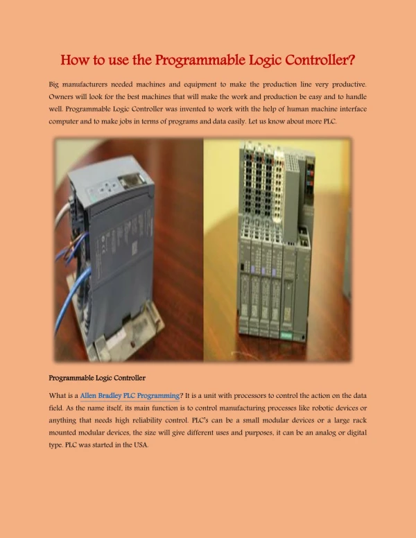
Definition of PLC • Programmable Logic Controllers are solid state devices that can be programmed to performed sequential and discrete state operation on external equipment • They are designed to perform the logic functions previously accomplished by electromechanical relays, drum switches, mechanical and electronic timers and counters, standalone digital PID controllers etc.
Major Manufacturer of PLC • Allen-Bradley (A-B) • General Electric • Gould-Madicon • Texas Instruments • Square-D • Reliance Electric • Siemens
Areas of PLC Applications Annunciators Injection Molding Auto Insertion Assembly Bagging Motor Winding Baking Oil Fields Blending Painting Boring Palletizers Brewing Pipelines Calendaring Polishing Casting Reactors Chemical Drilling Robots Color Mixing Rolling Compressors Security Systems Conveyors Stretch Wrap Cranes Slitting Crushing Sorting Cutting Stackers Digesters Stitching Drilling Stack Precipitators Electronic Testing Threading Elevators Tire Building Engine Test Stands Traffic Control Extrusion Textile Machine Forging Turbines Generators Turning Gluing Weaving Grinding Web Handling Heat Treating Welding
History of PLC • The Hydramatic Division of the General Motors Corporation specified the design criteria for the first • programmable controller in 1968. Their primary goal was to eliminate the high costs associated with inflexible, relay-controlled systems. The specifications required a solid-state system with computer flexibility able to • survive in an industrial environment, • Be easily programmed and maintained by plant engineers and technicians, and • (3) Be reusable. Such a control system would reduce machine downtime and • provide expandability for the future. Some of the initial specifications • included the following: • The new control system had to be price competitive with the use of relay systems. • The system had to be capable of sustaining an industrial environment. • The input and output interfaces had to be easily replaceable. • The controller had to be designed in modular form, so that subassemblies could be removed easily for replacement or repair. • The control system needed the capability to pass data collection to a central system. • The system had to be reusable. • The method used to program the controller had to be simple, so that it could be easily understood by plant personnel.
PLC and Computer • A PLC and a computer both are electronic processor unit. The architecture of a PLC’s CPU is basically same as that of a general purpose computer; however, some important characteristics set them apart. • Unlike computer, PLCs are specifically designed to survive the harsh conditions of the industrial environment. A well-designed PLC can be placed in an area with substantial amounts of electrical noise, electromagnetic interference, mechanical vibration, and noncondensing humidity. • Distinction of PLCs is that their hardware and software are designed for easy use by plant electricians and technicians. The hardware interfaces for connecting field devices are actually part of the PLC itself and are easily connected. • The modular and self-diagnosing interface circuits are able to pin point malfunctions and moreover, are easily removed and replaced. • Software programming uses conventional relay ladder symbols, or other easily learned languages, which are familiar to plant personnel. • A computer can execute a complex programming task and also multitasking. An standard PLC is designed to executes a single program in an orderly fashion. As PLCs are rapidly changing, modern PLCs have multitasking capabilities.
Why PLCs ? • Soft Manufacturing Process • Flexible Manufacturing Process • Retrofit Existing Process • Less Maintenance • Easy to Debug
Why PLCs are so Popular? • Programmable logic controller have made it possible to precisely control large process machines and driven equipment with less physical wiring and wiring time than it requires with standard electro-mechanical relays, pneumatic system, timers, drum switches, and so on. • The programmability allows for fast and easy changes in the relay ladder logic to meet the changing needs of the process or driven equipment without the need for expensive and time consuming rewiring process. • Modem PLCs are "electrician friendly", PLC can be programmed and used by plant engineers and maintenance electricians without much electronic and computer programming background. They can programmed by using the existing ladder diagrams.
Advantages of PLC A. Flexibility v Universal Controller - can replace various independent/ standalone controller. B. Implementing Changes and Correcting Errors v Do not have to rewiring relay panel. v Change program using keyboard. C. Large Quantity of Contact v Large number of' Soft Contact' available. D. Lower Cost v Advancement in technology and open architecture of PLC will reduce the market price. E. Pilot Running (Simulation Capability) v A program can be simulated or run without actual input connection.
Advantages of PLC • Visual Observation. • Can observe the opening and closing of contact switch on CRT . • Operator message can be programmed for each possible malfunction. • Speed of Operation • Depends on scan time -millisecond. • Asynchronous operation. • Ladder or Boolean Programming Method. • Easy for 'Electrician , • Reliability • In general -very reliable • Simplicity of Ordering Control Sys. Components • One package with Relay, Timers, Control Block, etc.
Advantages of PLC • Documentation • Printout of ladder logic can be printed easily • Security • Software lock on a program (Password) • Ease of Changes by Programming • Ability to program and reprogram, loading and down loading
Disadvantages of PLC • New Technology • Change from ladder and relay to PLC concept • Fixed program Application • Not cost effective for single- function application • Environment Consideration • Not adapted for very high temperature, high humidity level, high vibration, etc. • Fail-safe operation • Does not start automatically when power failure ( can be programmed into ) • Not "Fail-safe" -Fail-shorted rather than OPEN • Fixed-circuit operation • Fixed control system -less costly
What is a Ladder Diagram? A complete control scheme normally drawn as a series of contacts and coils arranged between two vertical control supply lines so that the horizontal lines of contacts appear similar to rungs of a ladder. The control contacts (input devices) are to left and coils (output devices) on the right. Ladder diagrams are an industrial standard for representing relay-logic control system
PLC Program and Data Files Program Files -Reserved Files (File # 0) -SFC file (File # 1 ) -Ladder file (File #2- 999) -File #2: Main Ladder File -Subroutine file (File #3 -999) -Selectable Interrupt file (File #3 -999) -Fault Routine File (File #3 -999) Data Files -Files which store data of the I/0 module. -Can be integer data, floating point (real) data, timer data, counter data, discrete input data, discrete output data, etc.