Programmable Controller Basics Introduction
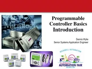
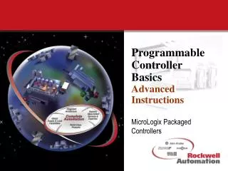
Programmable Controller Basics Introduction. MicroLogix Packaged Controllers. Traditional PLC Concept. PLC performs relay equivalent functions PLC performs ON/OFF control Ladder diagram program representation Designed for industrial environment Designed for ease of use and maintenance.

Programmable Controller Basics Introduction
E N D
Presentation Transcript
Programmable Controller BasicsIntroduction MicroLogix Packaged Controllers
Traditional PLC Concept • PLC performs relay equivalent functions • PLC performs ON/OFF control • Ladder diagram program representation • Designed for industrial environment • Designed for ease of use and maintenance
PLC Advantages • Ease of programming • Ease of maintenance • Designed for industrial environment • Quick installation • Adaptable to change
Today's Higher Level Control Capability • Arithmetic • Data Comparison • Word Manipulation • Master Control Relay Instructions • Program Skip Capability • Sequencing • Matrix Data Manipulation • Proportional, Integral, Differential (PID) Control
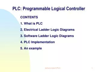
CR What Is A Programmable Controller? • A solid state device that controls output devices based on input status and a user developed program. • Originally developed to directly replace relays used for discrete control. Inputs Outputs Programmable Controller
Where do you Use a MicroPLC? • Conveyor control • Printed circuit board handling equipment • SCADA(Supervisory Control And Data Acquisition) • remote pump/lift station (water/wastewater) • Flow monitoring for leak detection (oil&gas) • Strapping machinery / trash compactors • Palletizers • Compressor control • Replace hard-wired relay panels or SBCs • Many, many more
Other Types of Control • MicroPLCs vs. Relays • above 2/3 relays cost becomes a problem • panel space, cost • limited functions • limited logic, no math, no application specific instructions • timers and counters cost $ to add • no communications • difficult to “exchange” data • maintenance/reliability • mechanical devices wear out, create and are affected by vibration • expensive to program • time consuming, difficult to document, hard to “pass on” logic • difficult to troubleshoot • requires skilled technician • “race” problems are common and difficult to deal with
Other Types of Control • MicroPLCs vs. Custom SBC’s (single board computers) • High design costs • Contract or Staff with overhead and maintenance issues associated with each • Repair / Service nightmare for customers • Depending on markets served supplier must develop/support services • High level of technical expertise required by technicians • Specialized circuit boards require specialized equipment and technical staff • Not readily available through distribution (typically regional) • Suppliers sell the controller imbedded, replacement parts are not readily available even in emergency situations • Typically does not meet worldwide standards • Certifications cost money, typically a single controller does not warrant the investment. Volumes are not high enough and re-certification on each revision is unrealistic • Typically a “Domestic” product • Because of these issues many manufacturers limit themselves to a single market.
Pushbuttons Selector Switches Limit Switches Level Switches Photoelectric Sensors Proximity Sensors Motor Starter Contacts Relay Contacts Thumbwheel Switches 120/230 VAC 24 VDC Sourcing Sinking Input Devices
Valves Motor Starters Solenoids Control Relays Alarms Lights Fans Horns Relays 120 VAC/VDC 240 VAC 24 VAC/VDC Triac 120/230 VAC Transistor MOSFET 24 VDC Output Devices
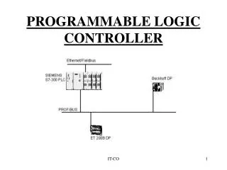
Communications Circuits Circuits Central Processor Input Output CR High Voltage High Voltage Isolation Barrier Isolation Barrier MEMORY data program Low Voltage AC Power Supply 85-264 VAC, 50/60Hz External DC Power Supply or Inside A PLC
Inputs/Outputs Type, AC, DC, sourcing, sinking, etc. Number of 10, 16, 20, 32, 156 Memory Type Flash or Battery backed Size 1k, 6k, 12k, 16k, 64k Functions required Instruction set Messaging PID PTO, PWM Arithmetic Communications DeviceNet, Ethernet Remote I/O, DH+ Report generation PLC Application Considerations
PLC’s Come in a Variety of Sizes... • Pico • Typically less than 20 I/O • Micro • Typically less than 32 I/O • Small • Typically less than 128 I/O • Medium • Typically less than 1024 I/O • Large • Typically greater than 1024 I/O
And a variety of shapes/configurations • Packaged • MicroLogix 1000,1200 and 1500 • Packaged with expansion • MicroLogix 1200 and 1500 • Modular (rack less) • MicroLogix 1200 and 1500 • Modular (rack based) • SLC 500 and PLC5 • Distributed • SLC 500 and PLC5
Packaged PLC • Power supply, inputs, outputs and communication port are enclosed in a single package. Input and output devices are wired individually to the packaged controller.
Packaged PLC With Expansion • Base is identical to the standard Packaged PLC, but it also has the ability to drive additional I/O. The most common form of expansion is a block of I/O that uses the same base, or makes use of different types of expansion “modules”.
+ + Compact I/O Processor Base Unit Modular Rack-Less PLC’s • Identical in functionality to rack based PLC’s • Typically not as robust (packaging) • Typically found on “smaller” (small and medium) sized PLC’s. • Will likely become the prevalent form of packaging in the future.
Modular PLC’s • Mix N Match Components • Processors, Power Supplies and I/O are plugged into a rack or chassis • Available in Small, Medium, and Large platforms • Flexibility results in higher costs when compared to packaged
Distributed • Rely on communications for EVERYTHING • All I/O is connected to the processor through a “High Speed” data link. • Typically found on “larger” (medium and large) PLC’s. • For certain applications this type of form factor is very advantageous. • Usually higher cost for hardware, but much lower cost for system integration. • RIO (Remote I/O), DeviceNet are examples of distributed control.
Why use a Micro PLC • Performance • Although small in size these products can perform the same tasks as much larger PLC’s • Cost • The price range for the entire family: $200-$800 List • Reliability • Designed to meet existing industrial design standards • UL, CSA, CE • Designed & manufactured in ISO9000 facilities • International Focus • Standard product available throughout the world
Typical PLC Application Solenoid 2 Solenoid 1 Motor Ingredient A Ingredient B Sensor 1 Sensor 2 Solenoid 3
Solenoid 1 On = Sol 3 is off, and Motor is off, and Sensor 2 is off, and Auto Switch is on Off = Sol 3 is on, or Motor is on, or Sensor 2 is on Solenoid 2 On = Sol 3 is off, and Motor is off, and Sensor 2 is on Off = Sol 3 is on, or Motor is on, or Sensor 1 is on Motor On = Sensor 1 is on, and Solenoid 2 is off, and Solenoid 1 is off Off = Solenoid 3 on Solenoid 3 On = Sol 1 is off, and Sol 2 is off, and Motor has run for 30 sec. Off = Solenoid 3 has been on for 60 sec. Solenoid 2 Solenoid 1 Motor Ingredient A Ingredient B Sensor 1 Sensor 2 Solenoid 3 Operation of Mixer
Input Wiring Isolation Barrier Terminal Block Input Devices 1 2 3 L1 4 PLC 5 L1 6 7 8 9 10 L2 COM
CR Output Wiring Isolation Barrier Terminal Block Output Devices L1 OUT 1 L2 OUT 1 OUT 2 OUT 2 PLC L1 OUT 3 L2 OUT 3 OUT 4 OUT 4 OUT 5 OUT 5 OUT 6 OUT 6
PLC Operating Cycle START Housekeeping Input Scan Internal checks on memory, speed and operation. Service any communication requests, etc. The status of external inputs (terminal block voltage) is written to the Input image (“Input file”). Output Scan Program Scan The Output Image data is transferred to the external output circuits, turning the output devices ON or OFF. Each ladder rung is scanned using the data in the Input file. The resulting status (Logic being solved) is written to the Output file (“Output Image”).