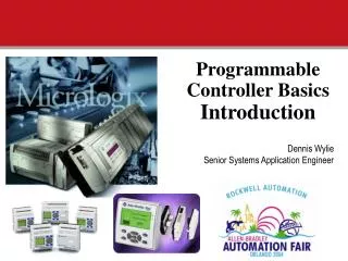
Programmable Controller Basics Introduction
Dennis Wylie Senior Systems Application Engineer. Programmable Controller Basics Introduction. So what is a P rogrammable L ogic C ontroller?. CR. A solid state device that controls output devices based on input signals and a user developed program.

Programmable Controller Basics Introduction
E N D
Presentation Transcript
Dennis Wylie Senior Systems Application Engineer Programmable Controller BasicsIntroduction
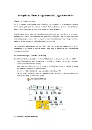
So what is a Programmable Logic Controller? CR • A solid state device that controls output devices based on input signals and a user developed program. • Originally developed to directly replace relays used for discrete control. Inputs Outputs Programmable Controller
What are typical Input devices for PLC’s? Type of Device Pushbuttons Selector Switches Limit Switches Level Switches Photoelectric Sensors Proximity Sensors Motor Starter Contacts Relay Contacts Thumbwheel Switches Temperature Sensors Device Ratings 120/240 VAC 24 VDC Sourcing Sinking 24 VAC 4-20mA 0-10VDC
What are typical output devices for PLC’s? Type of Device Valves Motor Starters Solenoids Control Relays Alarms Lights Fans Horns Heaters Device Ratings Relays 240 VAC 85-120 VAC/VDC 24 VAC/VDC Triac 120/230 VAC Transistor MOSFET 24 VDC 4-20mA 0-10VDC
General PLC Concept • PLC performs relay equivalent functions • PLC performs ON/OFF control • Ladder diagram program representation • Designed for industrial environment • Designed for ease of use and maintenance • Easy to program • Easy to maintain • Quick to install • Adaptable to change Great low cost alternative to multiple individual relays, timers and counters as well as dedicated single board controllers.
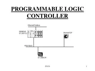
What's really inside a PLC? Communications RS-232 Circuits Circuits Central Processor (CPU) Input Output CR High Voltage High Voltage Isolation Barrier Isolation Barrier MEMORY data program Low Voltage AC Power Supply 85-264 VAC, 50/60Hz External DC Power Supply or
PLC’s Come in a Variety of Sizes... • Pico • Typically less than 20 I/O • Micro • Typically less than 32 I/O • Small • Typically less than 128 I/O • Medium • Typically less than 1024 I/O • Large • Typically greater than 1024 I/O
Today's Applications require high Level Control Capability • Arithmetic (Addition, Subtraction, Multiplication, Division, etc) • Data Comparison (Equal, Greater Than or Equal, Less Than or Equal) • Word Manipulation (Copy, Move, etc) • Sequencing • Data Manipulation • Proportional, Integral, Derivative (PID) Control
So where could you use a PLC? • Conveyor control • Printed circuit board handling equipment • SCADA(Supervisory Control And Data Acquisition) • remote pump/lift station (water/wastewater) • Flow monitoring for leak detection (oil&gas) • Strapping machinery / trash compactors • Palletizers • Compressor control • Replace hard-wired relay panels or SBCs • Many, many more
What to consider when applying a PLC Inputs/Outputs Type, AC, DC, Analog, Thermocouple sourcing, sinking, etc. Number of Inputs/Outputs including embedded, local expansion, and networked I/O 10, 16, 20, 32, 138, 156, >256 Memory Size 1k, 6k, 8k 12k, 14k, Functions required PID PTO/PWM (Pulse Train Output/Pulse Width Modulated) Data Logging Messaging between PLC’s Math Calculations Communications Networks DeviceNet, Ethernet DF1 Full Duplex, DF1 Half Duplex, DF1 Radio Modem, DH485, ModBus Master / Slave
Memory Organization DATA FILES 0 1 2 Output File Input File 3 4 Status File Bit File 5 6 Timer File 7 Counter File Control File Integer Files PROGRAM FILES 0 1 2 System 3 Reserved 4 5 Main Program Error File 6 - 15 HSC File STI File Subroutine Files MicroLogix MEMORY
PROGRAM FILES MicroLogix MEMORY 0 1 2 System 3 Reserved 4 5 PROGRAM FILES Main Program Error File 6 - 15 HSC File STI File Subroutine Files There are several different program files inside of a PLC. Lets talk about the main one we will use today.
File #2 = Main Program Dedicated & Open file • Main Ladder Program • Most important file • Typically is where the “main” user program resides • Must have some program logic • Where jump to subroutines originate
Data definitions and data types PLC Data Types Bit B3 file of PLC Integer (signed) -32768 to 32767 N7 file of PLC Floating Point F8 file of PLC ASCII String data “My Text String” Remember : Bits 1 or 0 Words (16 bits) 2 bytes
Programmable Controller BasicsAddressing the PLC instructions to real devices
Addressing Inputs and Outputs File #0 File Type Output Number Where the Output Was connected to the PLC O0:0/0 0 Outputs 11 0 File Number 0 0 0 0 0 0 0 0 0 0 0 0 Word 0 File Type File #1 Input Number Where the Input Was connected to the PLC I1:0/0 1 Inputs 15 0 File Number 0 0 0 0 0 0 0 0 0 0 0 0 0 0 0 0 Word 0
File #3 = Bit File 7 6 5 4 15 14 13 12 11 10 9 8 3 2 1 0 7 6 5 4 15 14 13 12 11 10 9 8 3 2 1 0 0000 0000 0000 0000 Word 0: B3:1/0 31 30 29 28 27 26 25 24 23 22 21 20 19 18 17 16 OR 7 6 5 4 15 14 13 12 11 10 9 8 3 2 1 0 0000 0000 0000 0000 Word 1: B/16 Bits in a PLC can be used to turn on a real device, or bits can be used as “storage”. They may just indicate when a condition exists within your program that you want to use in another part of your logic. For example, if the fact that a push button is pressed is important to the logic of your program, but additional conditions also need to be present for an real output to turn on, you may wish to store the state of the push button as a bit.
Timers I:0.0 | | 0 • Timer Operation The timer times as long as its rung conditions are TRUE. When the timer times up to a specified value, it alerts the rest of the program by setting a bit. When the rung becomes FALSE, the timer stops timing and resets itself to zero.
File #4 = Timers File Type Timer Number T4:0 File Number • File #4 • TON, TOF, and RTO • Timer On Delay (Turn On when the timer reaches preset value) • Timer Off Delay (Turn Off when the timer reaches preset value) • Retentive Timer On (Even after rung conditions are false this timer remembers where it left off.) • .01 and 1 second time base 4 Timers
Addressing Timers File Type Timer Number T4:0 15 14 13 File Number EN TT DN Word 0 Preset Value Word 1 Accumulated Value Word 2 4 Timers Preset T4:0.PRE How long the timer should time for. Accumulated T4:0.ACC How long the timer has timed for already. Done T4:0/DN Set to “1” when accumulated value > preset value. Timer Timing T4:0/TT Set to “1” when accumulated value < preset value. Enable T4:0/EN Set to “1” when the rung containing the timer is true.
Counters I:0.0 | | 0 • Counter Operation • The counter counts (by one) every time its rung goes from FALSE to TRUE. When a specified number of counts has been reached, the counter alerts the rest of the program by setting a bit. The program must reset the counter to start counting from zero again.
File #5 = Counters File Type Counter Number C5:0 File Number • Up, Down, and Up/Down Counters 5 Counters
Addressing Counters File Type Counter Number C5:0 12 11 15 14 13 Word 0 UN OV CU CD DN Preset Value Word 1 File Number Accumulated Value Word 2 5 Counters Preset C5:0.PRE How many the counter should count up to Accumulated C5:0.ACC How many the counter has counted already. Done C5:0/DN Set to “1” when accumulated value > preset value. Count Up C5:0/CU Set to “1” when state of CTU rung are true. Count Down C5:0/CD Set to “1” when state of CTD rung are true. Over/Underflow C5:0/OV,UN Set to “1” when counter counts past 32,767 or -32,768.
Programmable Controller BasicsSo what is ladder logic and how do I connect devices and write a program?
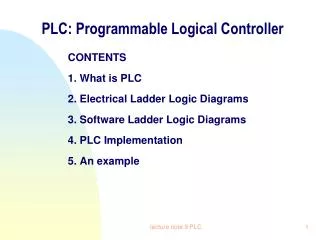
Relay Ladder Logic (RLL) • What is Relay Ladder Logic? • Is the primary programming language for PLCs • A graphical representation of the program designed to look like relay logic • Called ladder logic because it resembles the rungs of a step ladder you might have at home.
Conversion Example Relay Diagram to Ladder Logic SOL6 LS1 PS2 Relay Diagram Ladder Logic L1 L2 PB1 O/0 I/6 I/7 I/5 | | | | | | ( ) DEVICE NAME PB1 LS1 PS2 SOL6 PLC ADDRESS I:0/5 I:0/6 I:0/7 O:0/0
Addressing Input Instructions The instruction is: If the input device is The input bit is Examine OFF -|/|- XIO Examine ON -| |- XIC False True Open (0) Logic 0 True False Closed (1) Logic 1 These are not normally open (N.O.) and normally closed (N.C.) XIC = Examine When Closed, ON or when voltage is present XIO = Examine When Open, OFF or when voltage is not present
Addressing Output Instructions | | |/| ( ) T T T Rung State Output Terminal Output Bit ON ENERGIZED OTE Output Energize -( )- TRUE FALSE OFF De-energized
Ladder Logic Concepts Read / Conditional Instructions Write / Control Instructions |/| | | ( ) F T F No Logical Continuity |/| | | ( ) T T T Logical Continuity
Logical AND example I/4 I/5 O/0 | | | | ( ) IF input 4AND input 5 have power THEN energize output 0 On T T T Logical Continuity
Logical OR example I/4 O/0 | | ( ) I/5 | | I/4 O/0 | | ( ) I/5 | | IF input 4OR input 5 have power THEN energize output 0 T On Logical Continuity F F On Logical Continuity T
Example Timer Program Stop Motor Start Timer Done T4:0/DN I:0/1 O:0/3 I:0/0 ]/[ ]/[ ] [ ( ) M1 O:0/3 ] [ M1 TON O:0/3 (EN) ] [ TIMER ON DELAY Timer T4:0 Time Base 1.0 Preset 10 Accum 0 (DN) • The Timer’s “done bit” turns the motor off after a 10 second time delay
Example Counter Program Start I:0/0 ] [ M1 O:0/3 M1 O:0/3 (RES) • The Counters “done bit” stops the motor from running, after 10 operations. Stop Counter Done Motor C5:0/DN I:0/1 O:0/3 ]/[ ]/[ ( ) ] [ CTU (CU) ] [ Count Up Counter C5:0 Preset 10 Accum 0 (DN) Reset C5:0 I:0/4 ] [
Programmable Controller BasicsUnderstanding the PLC operating cycle and examining a real application.
Understanding the PLC Operating Cycle START Housekeeping Input Scan Internal checks on memory, speed and operation. Service any communication requests, etc. The status of external inputs (terminal block voltage) is written to the Input image (“Input file”). Output Scan Program Scan The Output Image data is transferred to the external output circuits, turning the output devices ON or OFF. Each ladder rung is scanned using the data in the Input file. The resulting status (Logic being solved) is written to the Output file (“Output Image”).
Typical PLC application Ingredient A Solenoid Valve 1 Ingredient B Solenoid Valve 2 Motor Ingredient A Ingredient B Sensor 1 Sensor 2 Start/ Stop Switch Drain Solenoid Valve 3
Sequence of Operation of the Mixer • Solenoid Valve 1 • On = Sol 3 is off, and Motor is off, and Sensor 2 is off, and Start Switch is on • Off = Sol 3 is on, or Motor is on, or Sensor 2 is on Step One: I need to add some ingredient A to the mixer, but I only want to do that when the mixer is empty, the drain is closed, and the motor is not running. Stop when I fill to Sensor 2 level. Step Two: I then need to add some ingredient B to the mixer, but I only want to do that after I’ve added enough ingredient A, the drain is closed, and the motor is not running. Stop when filled to Sensor 1 level. Solenoid Valve 2 Solenoid Valve 1 Motor Ingredient A Ingredient B Sensor 1 Automatic / Manual Switch • Solenoid Valve 2 • On = Sol 3 is off, and Motor is off, and Sensor 2 is on • Off = Sol 3 is on, or Motor is on, or Sensor 1 is on Sensor 2 Solenoid Valve 3
Sequence of Operation of the Mixer Solenoid Valve 2 Solenoid Valve 1 Motor Ingredient A Ingredient B Sensor 1 Sensor 2 Solenoid Valve 3 Step 3 Once I have added my ingredients, I need to mix them for 30 seconds, then I need to drain them from the vessel. I can close the drain after a minute of draining. Solenoid Valve 3 On = Sol 1 is off, and Sol 2 is off, and Motor has run for 30 sec. Off = Solenoid 3 has been on for 60 sec, Sol 1 is on, Sol 2 is on, motor is running. Automatic / Manual Switch Motor On = Sensor 1 is on, Sensor 2 is on and Sol 1 is off, Sol 2 is off, Sol 3 is off Off = Sol 3 on, Sol 1 is on, Sol 2 is on
So what are a few of the‘Killer’ applications that have been done with MicroLogix controllers?
Boot Scootin’ • Customer: Tait Towers • World renowned stage design • Concerts • Rolling Stones / U2 • Brooks & Dunn / Reba McEntire • Broadway • Phantom of the Opera • Miss Saigon • Television • MTV Video Music Awards • VH-1 Fashion Awards • Requirement: Solution to operate trendy “theater-in-the-round” set design with dramatic effects, flexibility of stage height, plus trouble-shooting capabilities so the show can go on! • MicroSolution: 17 MicroLogix 1000s and 1 SLC 500 control and coordinate: (Other products include: limit switches, motors, operator interface, contactors) • Motor driven raising/lowering of 2 band risers with variable height options • Rolling center deck to join both band pits • Fiery light show with 60 ft. tall “volcano” and drape
Monster Truckin’ • Customer: Dan Patrick • Designer and driver of monster trucks • Sampson • Requirement: Cost effective solution that provides accident-proofed muscle truck able to operate at max speed for most of race, and not require race-day repairs. • MicroSolution: 1 MicroLogix 1000 and Hand-Held Programmer: • Replaced relays • Controls shifting mechanism • Race 5-6 seconds long • 1.5 seconds to shift from 1st to 4th gear with 100 shifts per night • Keeps rpms steady by eliminating possibility of over-revving the motor • $300 control solution protects $55,000 investment in transmission and motor • Hand-Held Programmer trace key reduces troubleshooting time
“Operation MicroLogix” Customer: United States Army Requirement: Real-Time control of multiple targets on full scale 30 acre urban assault training site. MicroSolution: 330+ MicroLogix 1500 controllers and 1761-NET-ENI’s. • Pop-Up targets and count successful hits. • Communicate using Ethernet and Fiber Optic cables to all MicroLogix controllers. • Interface to advanced human interface software for control.