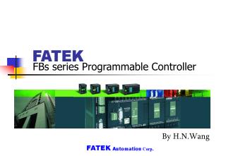
FBs series Programmable Controller
FBs series Programmable Controller. By H.N.Wang. Contents. Hardware integration Model of main units On board expansions I/O expansions Optional expansions Handheld PP and Data Access Panel. Contents. Functionality integration System specifications I/O Addressing Communications


FBs series Programmable Controller
E N D
Presentation Transcript
FBs series Programmable Controller By H.N.Wang
Contents Hardware integration • Model of main units • On board expansions • I/O expansions • Optional expansions • Handheld PP and Data Access Panel
Contents Functionality integration • System specifications • I/O Addressing • Communications • Interrupts • High Speed Counters & Timers • High Speed Pulse & PWM Output • Temperature Measurement & PID control • 7-segment & 16-segment Display
Model of Main Units Domain of the main unit • Economical main units -- MA • High Performance main units -- MC • NC Positioning main units – MN • Standard equipments for all main units • Power Supply • CPU Board with One Communication Port (Port 0 : RS-232 or USB)
Dimension of Main Units FBs-44MN FBs-60XX FBs-32XX FBs-40XX FBs-20XX FBs-24XX FBs-10XX FBs-14XX W:60mm H:90mm D:80mm W:90mm H:90mm D:80mm W:130mm H:90mm D:80mm W:175mm H:90mm D:80mm
Full Description of Main unit □□ : Number of I/O; 10/14/20/24/32/40/60 for MA/MC, 20/32/44 for MN Δ : Port 0 interface; Blank ̶ RS232, U ̶ USB ◇ : Transistor output type; Blank ̶ Sink (NPN), J ̶ Source (PNP) ◎ : Power supply; Blank ̶ 100~240VAC, D ̶ 24VDC X : Optional order for high speed input (120K Hz) of the MC main unit (1~6 points) Y : Optional order for high speed output (120K Hz) of the MC main unit (1~4 pts)
On Board Expansions Communication Boards *FBs-CBE is an Ethernet ↔ Serial converter through port 1 & 2 for interfacing
On Board Expansions Analog & Display & Memory Boards
I/O Expansions Digital Expansion Units (Built-in Power Supply) □ : Type of output; Blank ̶ Relay, T ̶ Transistor ◇ : Transistor output type; Blank ̶ Sink (NPN), J ̶ Source (PNP) ◎ : Power supply; Blank ̶ 100~240VAC, D ̶ 24VDC
I/O Expansions Digital Expansion Modules (W/o Power Supply) □ : Type of output; Blank ̶ Relay, T ̶ Transistor ◇ : Transistor output type; Blank ̶ Sink (NPN), J ̶ Source (PNP)
I/O Expansions Analog & Temperature Expansion Modules
I/O Expansions 7/16 Segment LED Display & Thumbwheel Switch Input Modules
Optional Expansions Communication Modules * Not supports at MA model *FBs-CMxxE is an Ethernet ↔ Serial converter through port 4 for interfacing
Optional Expansions Power Supply Modules & I/O Extension Box FBs-EPOW FBs-XTNR
Examples for I/O Addressing X0~X13 Y0~Y9 X14~X37 Y10~Y25 X38~X41 Y26~Y29 R3840~R3847 + + + FBs-24MC FBs-40EA FBs-32DGI FBs-8EA X0~X23 Y0~Y15 R3840 Y16~Y23 R3841~R3844 R3904~R3905 X24~X31 Y24~Y31 + + + FBs-40MC FBs-RTD6 FBs-4A2D FBs-16EA
Operation of the main unit Sequence operation : Cyclic Scan Input : > One Scan Time … > One Scan Time Housekeeping: Communications, Data swap, Hi-speed pulse output, Hi-speed counter, Time base generation, LED indication, • • • Get Input Solve Ladder Diagram Program Program memory Status memory + Put Output *Execution time of one cycle is called scan time, the scan time varies with the program’s execution *The duration of the input signal should stand more than one scan time for proper control
Communications Port 0
Communications Port 1
Communications Port 1
Communications Port 2
Communications Port 2
Communications Port 3 * * Not supports at MA model
Communications Port 3 * * Not supports at MA model
Communications Port 4 * * Not supports at MA model
Communications Port 4 * * Not supports at MA model
Communications Comm. port Item Note : LB means Low Byte ; HB means High Byte
Communications Setting for communication protocol • Method 1 High Byte Low Byte R4047 : Note : b0, b5 ~ b7 don’t care
Communications Setting for communication protocol • Method 2 High Byte Low Byte R4047 :
Communications Setting for communication parameters High Byte Low Byte
Communications Delay time to reply/Time span for no reply detection/Delay time to transmit next packet Master Slave Sending one packet of message Receiving one packet of message Start the time span timer for no reply detection Message for this station and passes error check ? No No reply Receive the reply message ? Yes Yes No Delay time to reply times up ? Time span timer times up ? No No Yes Delay time to TX next packet times up ? Yes Yes Set error code No Reply according to this packet of message Finish this packet of communication
Communications • Data flow • Simplex • Half duplex • Packet of message & Time interval to detect new packet • Synchronized by Start_of_Text & End_of_Text • Synchronized by time interval Master Slave Command No reply from slave Command Reply for this command Idle time over“Time interval to detect new packet” Character stream • • • ••• Idle time can’t exceed the“Time interval to detect new packet” .Time interval to detect new packet = 48 x 1/Baud Rate (M1956=0) = High Byte of R4148x 16/ Baud Rate (M1956 =1)
Communications Settings through the WinProladder utility Comm. Parameters Delay time to reply Delay time to TX next Time span for no reply detection Ignore station No. while HMI, SCADA Comm. Protocol Modem interface (Port 1 only)
Communication Protocols • FATEK communication protocol • Modbus RTU communication protocol • Modbus ASCII communication protocol
Communications • Comm. Port works as the communication slave • Port 0 : FATEK communication slave • Port 1 ~ 4 : FATEK, Modbus RTU/ASCII or User defined (FUN151 MD 2 instruction) communication slave • Port 1 : FATEK communication slave through MODEM (FBs-CB2x) • Port 1 : FATEK TCP/UDP communication slave through Ethernet (FBs-CBE) • Port 2 : Modbus TCP communication slave through Ethernet (FBs-CBE) • Port 4 : FATEK TCP/UDP or Modbus TCP communication slave through Ethernet (FBs-CMxxE) • Comm. Port works as the communication master • Port 1 ~ 4 : Master of the FATEK CPU Link (FUN151 MD 0) network through RS-232 or RS-485 interface • Port 1 ~ 4 : Master of the Modbus RTU/ASCII (FUN150) network through RS-232 or RS-485 interface • Port 1 ~ 4 : User defined (FUN151 MD 1 instruction) communication master • Port 1 : FATEK communication master through MODEM (FBs-CB2x) • Port 1 : ASCII file output for printing (FUN94) (FBs-CB2x) • Port 2 : Master of the FATEK High Speed CPU Link (FUN151 MD 3) network through RS-232 or RS-485 interface • Port 2 : Master of the FATEK CPU Link (FUN151 MD 0) through Ethernet (FBs-CBE) • Port 4 : Master of the FATEK CPU Link (FUN151 MD 0) through Ethernet (FBs-CMxxE)