Architectures for Delay/Disruption-Tolerant Networking Implementations for Space
240 likes | 270 Vues
Explore the architecture, underlying protocols, and design models for DTN implementations in space networking. Learn how DTN integrates different communication networks seamlessly. A study on DTN2 reference implementation and detailed hardware/software implementations are discussed.

Architectures for Delay/Disruption-Tolerant Networking Implementations for Space
E N D
Presentation Transcript
Architectures for Delay/Disruption Tolerant Networking Implementations for Space Authors Unnikrishnan E, Ravichandran V, Sudhakar S, Subramanya Udupa, (Indian Space Research Organization-ISRO, India)
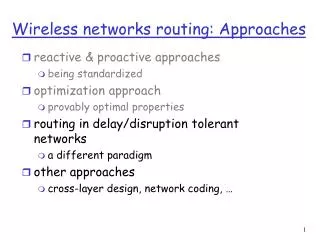
Overview Introduction to DTN DTN architecture Underlying protocols Study on DTN2 reference implementation Architectural components Design models for flight implementation Hardware implementation using VHDL Embedded processor based implementation Software implementation on SBC Conclusion
DTN Introduction • DTN protocol objective is to integrate networks of different communication characteristics, called regional networks, for seamless operation Eg. regional network: mobile network, sensor network, space network, terrestrial networks like Internet, etc. • Communication characteristics of a network include • connectivity (disruption or intermittency) • path delay (long) • error rate BER or packet loss (high) • data rate (asymmetric) • The underlying protocols are optimized for its characteristic for each network • Applications are made transparent to the above communication characteristics of individual networks for inter regional operation.
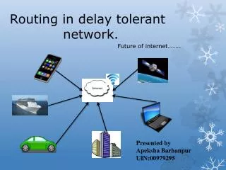
A typical DTN scenario Region Network B (Satellite Network) DTN GATEWAY DTN GATEWAY B C A B Network C (Internet) Region Network A (Sensor Network) Node C2 (user) NodeA1 (user) An illustrative diagram of DTN network
How DTN works Transport layer is terminated when there is a network partition (disruption /delay) A store and forward message switching mechanism is embedded in the network architecture Messages are stored in a persistent storage in this new architecture when networks are partitioned A new overlay protocol, called Bundle layer, is introduced above transport layer Bundles are moved towards destination for delivery on opportunistic and scheduled contacts
DTN Architecture Application Layer Application Layer Bundle layer Region Specific Layers Region Specific Layers Region Specific Layers Region Specific Layers Application Bundle layer Application Persistent storage Transport Transport (TCP) Network Network ( IP) Network specific layers Data Link Data link Physical Physical Internet layers DTN layers
Protocol Features Store and forward message switching Reliability and custody transfer Time stamp and time synchronization Routing and Forwarding Fragmentation and reassembly Congestion control Security
Bundle Processing control flags 0 -- Bundle is a fragment. 1 -- Application data unit is an administrative record. 2 -- Bundle must not be fragmented. 3 -- Custody transfer is requested. 4 -- Destination endpoint is a singleton. 5 -- Acknowledgement by application is requested. 6 -- Reserved for future use. Bits in positions 7 through 13 are used to indicate the bundle's class of service. Bit positions 8 &7 as follows: 00 = bulk, 01 = normal, 10 = expedited, 11 is reserved for future use. 14 -- Request reporting of bundle reception. 15 -- Request reporting of custody acceptance. 16 -- Request reporting of bundle forwarding. 17 -- Request reporting of bundle delivery. 18 -- Request reporting of bundle deletion. 19 -- Reserved for future use.
Administrative records Administrative record types : Bundle status report. Custody signal. Custody signal: Redundant reception Depleted storage. Destination endpoint ID unintelligible. No known route to destination No timely contact with next route Block unintelligible. Bundle status report: Reporting node received bundle. Reporting node accepted custody of bundle Reporting node forwarded the bundle Reporting node delivered the bundle Reporting node deleted the bundle.
Evaluation of DTN2 reference implementation • Configured and evaluated reference implementation DTN2 on a Linux test bed • Simulated DTN operation for a typical configuration of a ground node, orbiter and a rover on the test bed • Simulated command file delivery to rover and telemetry reception at ground for intermittently connected links (LAN) • Proved the concept of DTN operation over disrupted link where other protocols fail to operate • Contact Graph based routing was configured
DTN simulation test bed Simulated as Ground node Simulated as Orbiter Simulated as Rover received command file PC DTN Node-1 PC DTN Node-2 PC DTN Node-3 link 1 link 2 telemetry file command file LAN Links are disrupted using test scripts Contact graphs are maintained at each node with scheduled connectivity DTN simulation test bed
DTN prototype on FPGA(hardware implementation) Specification (scaled down) • EID is singleton (only unicast is supported) • Storage – 4 memory blocks • DTN Timer resolution - 1ms • Priority levels – 3 • Life time of bundle – 10 minutes • Bundle size – 1024 bytes (primary block 64 bytes + 4 bytes payload block + 956 bytes payload ADU) • SDNV encoding / decoding • Contact graph based routing • Security (not addressed)
Test setup for prototype validation Test setup of DTN prototype implementations on FPFA Hardware Xilinx vertex-4 FPGA XC4VFX60 Software ISE Design Suite 13.4, ModelSim SE 6.4 Coding Language – VHDL System frequency – 4MHz Simulation test done
Major VHDL modules DTN Node UART TX/RX Top bundle protocol module Top transmitter module Top receiver module Administrative record Persistent storage Header formation Payload block formation RAM modules SDNV encoding SDNV decoding Clock generation UART module (testing with I/O data) UART RX SDNV encode & Bundle formation Persistent storage Forward Module SDNV and block decoding UART TX Extract ADU
DTN prototype hardware-software implementation Core8051, an Intel compatible 8 bit microcontroller, executes all ASM51 instructions with RISC like design System frequency 12MHz Coding language –VHDL Libero IDE 9.0, ModelSim SE 6.5d Open Keil uVision 3 H/W Xilinx vertex4 FPGA XC4VFX60 FPGA (Xilinx) Core8051soft core RAM (component ) PROM (component ) • Core8051 is chosen as an embedded processor platform to prove the concept • DTN basic modules ‘hex code’ is loaded on PROM to validate the platform • DTN modules are tested independently to port to the target
Software Design approach Bundle Protocol Server Convergence Bundle Protocol Agent Application Agent Contacts Registration Naming Routing Commands Utilities Convergence layer Top level package level design
Design approaches Standard defines a DTN Node as • Single process running on a general purpose computer • Thread in a process • An object in an object oriented system • A special purpose hardware device • .... Embedded processor OS Monolithic hardware design (collection of hardware modules) Processor H/W OS (optional) software modules software modules Hardware implementation Hardware software implementation Software implementation
DTN /BP DTN/BP Prox-1 LTP TM /TC APPLN DTN/BP Prox-1 DTN /BP LTP TM /TC APPLN DTN Application envisaged APPLN DTN/BP Orbiter AX.25 Lander APPLN rover DTN/BP AX.25 DTN/BP planetary surface TCP/IP Ground station DTN/BP TCP/IP MCC Protocol stack diagram for envisaged space DTN network Earth
Conclusion • Results of the study on DTN-2 reference implementation are promising for its usage on a disconnected network. • For DTN for space a highly reliable and light weight version of the protocol suit is required. • Different design approaches are compared and efforts for prototyping were summarized • Protocol implementations need to undergo sufficient testing on simulators for all possible end to end scenarios • More simulations at ground are required for introducing dynamic routing of bundles for a large network • CCSDS standards on the DTN protocols help the space agencies to deploy an interoperable network for future
References Rationale, Scenarios, and Requirements for DTN in Space Informational Report CCSDS 734.0 G-1August 2010 CCSDS Bundle Protocol Specification Recommended Standard CCSDS 734.2 B-1 September 2015 RFC 5050 Bundle Protocol Specification ,Network Working Group Category: Experimental 2007 RFC 4838 Delay-Tolerant Networking Architecture, Network Working Group Category: Informational 2007 Solar System Internetwork Architecture Informational Report CCSDS 730.1 G-1July 2014 Report of the Interagency Operations Advisory Group Space Internetworking Strategy Group Recommendations on a Strategy for Space Internetworking July 2008 Licklider Transport Protocol (LTP) for CCSDS 734.1 B-1 May 2015 Proximity-1 Space Link Protocol— Data Link Layer CCSDS 211.0-B-5 December 2013 “Design of DTN for Interplanetary Communication” ,M Tech Thesis, Samreen Fiza , Project work done at TMD/DSG/CDA/ISAC 2013-14 “Design of a Platform for embedded applications using 8051 IP core”, M Tech Thesis, Pranam Amin, Project work done at TMD/CDEG/CDA/ISAC 2014-15 “Design and Modeling of DTN Bundling Protocol”, Deepak N A, Unnikrishnan E, et al International Conference on Modeling and Simulation August 2007
Thank you Acknowledgement to Dr. M Annadurai, Director ISRO, Satellite Centre