Download
1 / 74
740 likes | 841 Vues
Explore the history, technology, uses, and common systems of satellite communications, including satellite orbits and key figures in its development.

E N D
Overview ofSatellite Communications Dick McClure
Agenda • Background • History • Introduction to Satcom Technology • Ground System • Antennas • Satellite technology • Geosynchronous orbit • Antenna coverage patterns
COMMUNICATION SATELLITES • Uses • Example satellite systems
Why Satellite Communications? • Satellite coverage spans great distances • A satellite can directly connect points separated by 1000’s of miles • A satellite can broadcast to 1000’s of homes/businesses/military installations simultaneously • A satellite can be reached from ground facilities that move • Satellites can connect to locations with no infrastructure • Satellites adapt easily to changing requirements
Some Common SATCOM Systems • The INTELSAT system • provides globe-spanning TV coverage • The Thuraya satellite-based phone system • covers all of Saudi Arabia and Egypt • DoD Military Communications Satellite System • Links field sites with Pentagon and US command centers • DirecTV, Echostar • Direct-to-home TV • XM Radio, Sirius • Satellite radio-to-car/home • Hughes VSAT (Very Small Aperture Terminal) systems • Links GM car dealers, Walmart, Costco, J C Penney, etc. to their accounting centers
Common Satellite Orbits • LEO (Low Earth Orbit) • Close to Earth • Photo satellites – 250 miles • Iridium – 490 miles • Polar Orbit • Provides coverage to polar regions (used by Russian satellites) • GEO (Geosynchronous Earth Orbit) • Angular velocity of the satellite = angular velocity of earth satellite appears to be fixed in space • Most widely used since ground antennas need not move • Circular orbit • Altitude: 22,236 miles • Can’t “see” the poles
HISTORICAL BACKGROUND • People • Early satellites • Evolution
Historical Background:People • Arthur C. Clarke • Highly successful science fiction author • First to define geosynchronous communications satellite concept • Published paper in Wireless World, October 1945 • Suggested terrestrial point-to-point relays would be made obsolete by satellites • Unsure about how satellites would be powered • John R. Pierce – Bell Telephone Laboratories • Directed seminal work in the ’50’s on communications satellites at Bell Labs • Harold C. Rosen - Hughes Aircraft Company • Led team that developed practical geosynchronous communications satellite • Key contribution: spin stabilization • Rotational inertia maintains pointing with small fuel requirement • First geosynchronous satellite: Syncom II – July 26, 1963
Historical Background:Early Communications Satellites • Echo – NASA • First communications satellite (passive) • 100 foot diameter metallized balloon – 12.7 mil Mylar polyester film • Echo 1A launched August 12, 1960 • Telstar – built entirely by Bell Telephone Laboratories; funded by AT&T • First active communications satellite • Launched July 10, 1962 by NASA • Low elliptical orbit (not geosynchronous) • Relay – built by RCA; funded by NASA • First NASA communications satellite; experimental • Launched December 16, 1962 • First to use Traveling Wave Tube in its transponder • Relay TWT.gif • Syncom – built by Hughes; funded by NASA and DoD • First geosynchronous communications satellite; experimental • Launched July 26, 1963 • Early Bird – built by Hughes; funded by Communications Satellite Corporation • First commercial geosynchronous communications satellite • Launched April 6, 1965 • “Live via Early Bird”
Satcom Timeline • 1950’s: Navy: D.C.Hawaii Teletype Link via the Moon • 1957: Sputnik • 1958: SCORE • 1960: Project Westford a.k.a. “Project Needles” • 1961: Echo • 1962: Telstar (spinning satellite) • 1962: Relay “ • 1963: Syncom “ • 1965: Early Bird/Intelsat I “ • 1974: Intelsat IV (spinning body, ‘de-spun’ antennas)
Cellular-to-Satellite Comparison • User • Cell site • Central office • Cell site • User • User • Ground Terminal • Satellite • Ground Terminal • User
End-to-end Satcom Picture Phone Satellite ground station Long-haul link Phone system Examples: cellular, cellular plus wired, wired Examples: copper, fiber, LOS microwave Generic satellite components Receive antenna Transmit antenna Frequency converter Receiver Transmitter Receive and transmit frequencies must be different to avoid interference Amplify weak received signal Amplify weak signal; contribute little noise of its own Phone Long-haul link Satellite ground station Phone system
Satellite Communications Terminology Ground station (also “ground terminal”) sends signals to/receives signals from a satellite Modulator, demodulator (modulator + demodulator = modem) Ground station component: modulator converts digital “1”s and “0”s to a radio frequency signal (modulated carrier) that can be transmitted Demodulator recovers digital “1”s and “0”s from the modullated carrier Carrier frequency The center frequency of a modulated carrier Frequency band The frequency range containing the carrier frequency Satellite communications frequency bands are standardized Within the US, the FCC defines frequency bands for satcom; coordinates specific frequency assignments; Outside the US, the International Telecommunications Union has the same role Frequency conversion (up-conversion, down-conversion) The process by which the carrier frequency is changed to accommodate standards or hardware limitations Up-link – the link from the ground terminal to the satellite Down-link – the link from the satellite to the ground terminal 14
Satellite Communications Process • Digital information from user arrives at a “ground station”. • Digital signal goes into a modulator, converting digital information into a modulated carrier. • Carrier frequency is changed (up-converted) to place it in the desired frequency range (up-link frequency band) for transmission to the satellite • Carrier is amplified • The ground station antenna radiates the carrier toward the satellite • The signal passes through earth’s atmosphere (~10 miles thick) and continues on to satellite ~22,300 miles away • The satellite receives signal and changes (down-converts) the carrier frequency to the down-link frequency band. • The satellite amplifies the carrier • Amplified carrier is re-radiated toward earth through the satellite antenna. • Received carrier is picked up by earth station antenna, amplified, and changed to a frequency that the demodulator can process. • Demodulator recovers original digital information from carrier, though not perfectly; errors are always present!
Ground Terminal Transmitting Subsystem RF signal summer: Collects signals on multiple frequencies onto a single connector f1 Σ RF Signal Summer Modulator 1 f2 Modulator2 Input Voice/ Data Signals Transmitter Antenna f3 Modulator 3 Up-Converter Antenna: converts conducted energy into radiated energy; focuses and directs signal emission fn Modulator n Up-converter: raises signal frequency to a range where transmission and/or filtering is realizable 17
Ground Terminal Receiving Subsystem RF signal splitter: provides multiple signals that can be individually processed RF Signal Splitter ÷ Demodulator 1 Demodulator 2 Low-Noise Amplifier Antenna Down- Converter Demodulator 3 Antenna: Intercepts signal emission from space; converts radiated energy into conducted energy Down-converter: drops signal frequency to a range where desired processing (filtering, demodulation) is realizable Demodulator n 18
Antenna Key Points One antenna talks to only one satellite! Antenna-satellite association must be unique to avoid interference Small antennas have advantage of compactness, but Communications design for ground terminals with small antennas requires care to avoid interference 20
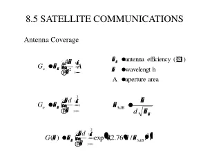
Earth Station Antenna Pointing Geometry Elevation angle – 0° to 90° Elevation axis High elevation angle Low elevation angle Local horizontal Local horizontal North North North Az = 210° Az = 60° Azimuth axis Az = 310° Azimuth angle – 0° to 360° 21
Antenna GeometryFocus-fed Design Advantage: simple design; Disadvantage: distance to feed from electronics Circular Parabolic Reflector (surface accuracy related to signal wavelength) Signal Input/output Feed (at focus of parabola) Lines indicate ray-paths traversed by radio-frequency energy passing to or from the antenna feed (similar to light rays) One antenna talks to only one satellite! 22
Antenna GeometryCassegrain Design Advantage: feed can be close to electronics, minimizing losses; Disadvantage: more expensive - requires subreflector The parallel lines represent the signal direction near the antenna Circular Parabolic Main Reflector Signal Input/output Circular Hyperbolic Subreflector Feed (at reflected focus) 23
Antenna GeometryOffset-fed Design Advantage: Easily adaptable to roof-top mounting for mobile (truck-mounted) applications; Disadvantage: distance to feed from electronics Circular Parabolic Reflector Segment (half of a parabola) Signal Input/output Feed (at focus of parabola) 24
Antenna GeometryGregorian Design Advantages: Compact; easily adaptable to roof-top mounting for mobile (truck-mounted) applications; feed can be close to electronics Disadvantages: distance to feed from electronics; expensive to manufacture Circular Parabolic Main Reflector Segment (half of a parabola) Signal Input/output Circular Hyperbolic Subreflector Feed (at reflected focus) 25
Antenna Beamwidth: Two Views Beamwidth: the angle off the axis of the beam where the emitted power is half that at the on-axis peak of the beam. Beamwidth is expressed in degrees. Contour indicates relative signal strength; strongest on axis, weaker to the sides Beamwidth Power = 1/2 Power = 1 Power = 1/2 Antenna Location Though not strictly accurate, it’s helpful to visualize the beam from an antenna as a cone whose total angle equals the antenna beamwidth: Beam width Power = 1/2 Beam axis 26 Power = 1/2
Antenna Size vs. Beamwidth Antenna Location Smaller Antenna → • Wider beamwidth • Lower gain • Less precise pointing requirement Beamwidth (smaller antenna) Relative signal strength Antenna Location Larger antenna → • Narrower beamwidth • Higher gain • More precise pointing requirement Beamwidth (larger antenna) 27
COMMUNICATIONS SATELLITES • Types • Electronics • Orbits • Launch Sequence
Types of Communications Satellites “Bent-pipe” satellites (“repeater in the sky”) What comes down = what goes up Example satellites: US domestic, Intelsat, Panamsat Processing satellites What comes down may be (slightly) different from what has gone up With demodulation Iridium Routing determined from message headers Without demodulation Thuraya Spaceway WGS Up-loadable stored-program switching Digital signal processing used to route traffic of varying bandwidths between/within beams 29
Typical Satellite Receiver Section ÷ to further down- conversion or processing Down Converter 1 RF Signal Splitter Down Converter 2 Antenna Down Converter 3 RF signal splitter: provides multiple signals that can be individually processed Low-Noise Amplifier Antenna: Intercepts signal emission from earth; converts radiated energy into conducted energy Down-converter: drops signal frequency to an intermedate range where desired processing (filtering, demodulation) is realizable Down Converter n 30
Typical Satellite Transmitter Subsystem Up-converter: raises signal frequency to a range where transmission and/or filtering is realizable f1 Σ RF Signal Summer Up Converter 1 f2 RF signal summer: combines signals on multiple frequencies into a common transmitter Up Converter 2 Intermediate frequency from receiver or signal processing Antenna f3 Up Converter 3 Antenna: converts conducted energy into radiated energy; focuses and directs signal emission Transmitter Transmitter: High power; moderate distortion; moderate noise fn Up Converter n 31
Communications Satellite Components • Bus • Power System • Command and Telemetry System • Propulsion System • Communications Payload • Antennas • Receiver • Processor • Transmitter
Satellite Power System • Solar cells are power source • Solar cell array length: 5 – 100 feet • Primary power: up to 18,000 watts • Arrays fold to fit in booster “fairing”; unfurl following launch • Batteries maintain constant power levels during eclipse • Power is regulated for electronics
Geosynchronous Orbit Geometry(View from the North Pole) • Key point: in geosynchronous orbit, satellite rotates at precisely the same angular velocity as does the earth; from earth, satellite appears to remain motionless • Geosynchronous orbit altitude above earth: 22,236 statute miles • Earth radius: 3,963 statute miles • Angle subtended by earth from satellite: 17.2° Orbit radius: 22,236 + 3,963 = 26,199 mi. Earth radius: 3,963 miles (at the equator) Orbit track North Pole Orbit Altitude = 22,236 miles Satellite rotation about center of earth 17.2° Earth rotation
Geosynchronous Orbit Geometry(View at the Equator) • Highest latitude at which satellite can be seen = 81° North Pole (90° Latitude) Satellite motion is into the slide 81° 22,236 miles Equator (0° Latitude)
Transfer Orbit Apogee (farthest distance from earth) GeosynchronousLaunch OrbitSequence 1. Launch from Cape Kennedy 2. Satellite is launched Into Parking Orbit 3. Rocket is fired to boost satellite into Transfer Orbit 4. Apogee Kick Motor Is fired to place satellite in Geosynchronous Orbit 22,236 miles Transfer Orbit Perigee (closest distance to earth)
Frequency Usage • Key point: uplink and down link signals always on different frequencies • Reason: interference control on ground and at satellite • Band and frequency assignments authorized by FCC (US domestic) and ITU (International Telecommunications Union; non-US) • frequencies used by US military/DoD outside US selected to meet ITU recommendations • FCC and ITU promote regulations on ground terminals to control interference between users
Electromagnetic Frequency Spectrumwith Satcom Band Designations FM Radio Cellular RF (>~100 kHz) dc (100 Hz) B’cast TV AM Radio Audio Satellite Hz 101 102 103 104 105 106 107 108 109 1010 1011 1 kHz 1 MHz 1 GHz 100 GHz X Rx 7.25 – 7.75 X Tx 7.9 – 8.4 C Rx 3.4 – 4.2 C Tx 5.6 – 6.4 Ku Rx 10.9 – 12.7 Ku Tx 13.8 – 14.5 IR, visible light, UV (~6 x 10¹⁴ Hz) S 1 GHz 3 GHz 5 GHz 7 10 GHz 30 GHz 50 GHz 70 100 GHz 109 Hz 1010 Hz 1011 Hz WGS: Ka Rx 20.2 – 21.2 WGS: Ka Tx 30.0 – 31.0 Rx: receive Tx: transmit
ITAC INTELSAT, DirecTV downlink, others DirecTV uplink, others (Globalstar Transmit) (Globalstar Receive) INTELSAT WGS 137 - 150 1.98- 2.5 GHz 1.5 - 2.0 GHz 3.9 20.2 31 6.3 11 14.5 17.3 20.2 K Ku VHF C L S Ka 3 GHz 30 GHz 300 MHz UHF SHF EHF 75GHz 40GHz 4GHz 8GHz 1GHz 2 GHz VHF 18GHz 27GHz 12GHz L S C X Ku Ka W V 110 GHz 30-31 GHz Space-Ground Link System (SGLS) Global Positioning System (GPS) MILSTAR, WGS, GBS DSCS AF / FLT SATCOM UFO Military Air/Ground Radios WGS, GBS L5: 1.17645 GHz L2: 1.22760 GHz L1: 1.57542 GHz 7.25-7.75 GHz 1.761-1.842 GHz uplinks 2.200-2.290 GHz downlinks DSCS 20.2- 21.2 GHz 225-400 MHz 138-144 MHz 7.9-8.4 GHz Unified S-Band (USB) Milstar Crosslinks MILSTAR 2.025-2.110 GHz uplinks 2.200-2.290 GHz downlinks 43-45 GHz 60 GHz = Used as Uplink Band = Used as Downlink Band Adapted from chart published by Satcom Frequency Usage
Frequency Domain Terminology • Baseband: • the signal that is received from the user(s) – may be digital or analog; • the input to the modulator; • the output from the demodulator • IF (Intermediate Frequency) • a (relatively) low frequency which the modulator emits or the demodulator accepts; the frequency of the carrier from the modulator; • typical IF frequencies: 70 MHz, 140 MHz • RF (Radio Frequency) • a (relatively) high frequency at which a transmitter or receiver operates; • typical frequency ranges: X-band (7.25 – 7.75 GHz ground receive; 7.9 – 8.4 GHz ground transmit); • Ka-band: 30-31 GHz ground transmit; 20.2 – 21.2 GHz ground receive • Note: these definitions are only samples; all baseband signals don’t go into a modulator; IF frequencies may be other than 70/140 MHz, etc.
PHASED ARRAY SATELLITE ANTENNA CONCEPTS 43
Amplifiers RF Input Phase Shifters (values are equal) Phase Shifters (Differences are equal) Radiating Elements Phased Array Concept:Transmission with variable aiming Wavefront is perpendicular to array when phase difference between array elements is equal to zero Emitted Beam Emitted Beam Wavefront is at a slant to array when phase difference between array elements is equal and non-zero
Phased Array Concept:Two Signals; Two Beams Amplifiers RF Signal 1 Beam 1 Phase Shifters RF Signal 1 RF Signal 2 Beam 2 RF Signal 2 Radiating Elements Note: Signals 1 and 2 must be on different frequencies Phase Shifters
~49” ~42” ~32” Phased Array Cartoon:One array – four beams Phased Array Aperture
Link Analysis • Goal: determine the conditions under which an adequate signal-to-noise ratio is available • Link budget: an analysis of losses between transmitter and receiver, and noise sources impacting the receiver
Link Analysis • Uplink: • Carrier power: Pr = Pt + Gt - FSL - La + Gr • Pr : satellite received carrier power • Pt : ground transmitted power (into antenna) • Gt : ground transmit antenna gain • FSL: Free Space Loss • La : atmospheric losses • Gr : spacecraft receive antenna gain • Noise Power: Nr = kTrB + kTuB + Ni • Nr : satellite received noise power • Tr: receiver noise temperature • Tu: uplink noise (earth thermal noise, sky noise “seen” by antenna) • Ti : interference noise temperature • B: noise bandwidth • C/Nu = Pr – Nr = Pt + Gt – FSL – La + Gr – (k Tr B +kTuB + kTiB) = e.i.r.p.u – FSL – La + Gr – [k + 10 log(Tr sat +Tu + Ti) + B]
Link Analysis • Downlink: • Carrier power: Pr = Pt + Gt - FSL - La + Gr • Pr : ground received carrier power • Pt : satellite transmitted power (into antenna) • Gt : satellite transmit antenna gain • FSL: Free Space Loss • La : atmospheric losses • Gr : ground receive antenna gain • Noise Power: Nr = kTrB + kTeB • Nr: ground receiver noise power • Tr: ground receiver noise temperature • Te: atmospheric noise (sky thermal noise) • B: noise bandwidth • C/Nd = Pr – Nr = Pt + Gt – FSL – La + Gr – (kTrB + kTeB) = e.i.r.p.d – FSL – La + (Gr /Tr)es(1/kB) – kTeB