Download
1 / 53
590 likes | 1.36k Vues
FIGURE 19–1 Bendix 9 ABS contains nine solenoids and was used on older model Jeeps. FIGURE 19–2 Bendix 10 systems use four isolation valves, three decay valves, and three build valves. FIGURE 19–3 Bendix 10 hydraulic control unit. FIGURE 19–4 Bendix 6 ABS is a nonintegral system.

E N D
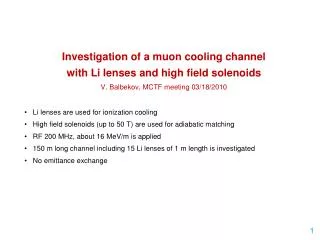
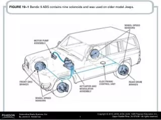
FIGURE 19–1 Bendix 9 ABS contains nine solenoids and was used on older model Jeeps.
FIGURE 19–2 Bendix 10 systems use four isolation valves, three decay valves, and three build valves.
FIGURE 19–5 Bendix 6 schematic showing the normal braking mode (pressure increase stage).
FIGURE 19–10 The wiring schematic for the Bendix ABX-4 hydraulic control unit.
FIGURE 19–11 Bendix ABX-4 wiring harness and component locations.
FIGURE 19–12 Bendix Mecatronic modulator controls ABS and drive wheel traction during acceleration.
FIGURE 19–13 Bendix Mecatronic system with traction control showing component locations.
FIGURE 19–14 Bendix Mecatronic throttle actuator pushes back the throttle linkage to help reduce wheel spin by reducing engine torque.
FIGURE 19–15 Bosch 2 ABS system showing the location of the components.
FIGURE 19–19 Bosch ABS/ASR system in the pressure hold mode.
FIGURE 19–20 Bosch ABS/ASR system in the pressure decrease mode.
FIGURE 19–23 Delphi ABS-VI modulator, motor pack, and master cylinder.
FIGURE 19–26 Delphi ABS-VI expansion spring back (ESB) construction and operation.
FIGURE 19–27 Delphi ABS-VI system is pressure decrease mode for one front brake circuit.
FIGURE 19–28 Delphi ABS-VI system in the pressure increase mode for one front brake circuit.
FIGURE 19–29 Delphi ABS-VI system in pressure decrease for a rear brake.
FIGURE 19–32 Kelsey-Hayes RWAL system modulator in the normal brake mode (pressure increase mode).
FIGURE 19–33 Kelsey-Hayes system modulator in the pressure hold mode.
FIGURE 19–34 Kelsey-Hayes system modulator in the pressure decrease mode (pressure dump mode).
FIGURE 19–36 Kelsey-Hayes 4WAL electrohydraulic control unit (EHCU).
FIGURE 19–37 Kelsey-Hayes 4WAL system hydraulic schematic in the normal (pressure increase) mode.
FIGURE 19–39 Component location for the Kelsey-Hayes EBC5H four-wheel ABS system.
FIGURE 19–40 Hydraulic schematic of the Kelsey-Hayes EBC410 four-channel ABS system.
FIGURE 19–43 Teves Mark IV nonintegral ABS hydraulic circuit.
FIGURE 19–45 Teves Mark 20 ABS system on a typical rear-wheel-drive application.
FIGURE 19–46 Teves Mark 20 ABS system on a typical front-wheel-drive application.
FIGURE 19–47 Teves Mark 20 ABS systems with traction control use a master cylinder that has center valves to allow the brake fluid to flow from the master cylinder reservoir.
FIGURE 19–48 The integrated control unit (ICU) is used on most Mark 20 ABS applications.
FIGURE 19–49 The deceleration sensor in Teves Mark 20 ABS systems used on Jeep applications uses three mercury switches that open in response to forward and reverse deceleration forces.
FIGURE 19–50 Component location of the Toyota rear-wheel ABS system.