Download
1 / 55
560 likes | 984 Vues
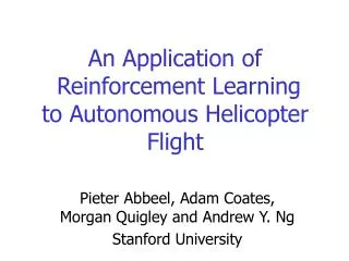
A Flight Control System for Autonomous Helicopter. People. Group Members: Jacky, SHEN Jie Frank, WANG Tao Marl, MA Mo Supervisors: Prof. QIU Li Prof. LI Zexiang. Presentation Flow. Introduction Controlling a Model Helicopter Attitude Estimation Hardware and Software

E N D
People • Group Members: Jacky, SHEN Jie Frank, WANG Tao Marl, MA Mo • Supervisors: Prof. QIU Li Prof. LI Zexiang
Presentation Flow • Introduction • Controlling a Model Helicopter • Attitude Estimation • Hardware and Software • Results and Further Work
Introduction What is an Autonomous Helicopter??
IntroductionWhat is Autonomous Helicopter? An Autonomous Helicopter is a helicopter who is fully or semi- controlled by on-board intelligence and computing power. Pictures are from CMU: http://www-2.cs.cmu.edu/afs/cs/project/chopper
What could an Autonomous Helicopter do? • Fly to a designated area on a prescribed path while avoiding obstacles. • Search and locate object of interest in the designated area. • Visually lock on to and track or, if necessary, pursue the objects. • Send back images to a ground station while tracking the objects.
What could an Autonomous Helicopter do? Pictures are from CMU: http://www-2.cs.cmu.edu/afs/cs/project/chopper/www/goals.html
Objectives and Goal • Step 1: On-board electronic system development • Step 2: Data collection from human controlled flights • Step 3: Algorithm simulations in PC • Step 4: On-board real-time algorithm implementation and testing • Goal: Achieving a hover flight
Controlling a Helicopter- Dynamic Model From MIT: http://gewurtz.lids.mit.edu/index.htm
Controlling a Helicopter- Dynamic Model From MIT: http://gewurtz.lids.mit.edu/index.htm • u, v, w, the velocity in x, y, z axis • p, q, r, the angle velocity in 3 axis • Θ, pitch, Φ, yaw
Controller Result • Successfully achieved a hover flight • Flied forward, backward and sideward • Flied on a prefixed path
Flight Controller Demonstration A small demonstration of autonomous helicopter controller
Information needed by flight controller The parameter we need to estimate: Body orientation: pitch, roll, yaw Body linear velocity vector: Vb (u, v, w) Body angular velocity vector: Wb (p, q, r) NED position : x, y, z
The complementary property of attitude estimation by gyro and gravity vector
The complementary property of body velocity estimation by GPS and body acceleration integration
What is Kalman fitler? The Kalman filter is a multiple-input, multiple-output digital filter that can optimally estimate, in real time, the states of a system based on its noisy outputs. The Kalman filter estimates a process by using a form of feedback control: the filter estimates the process state at some time and then obtains feedback in the form of (noisy) measurements.
The Kalman filter x: actual state vector z: measurement vector w: process variance v: measurement variance u: control input
Gyro noise variance Can be calculated from gyro reading orientation state: Pitch, roll, yaw
Variance introduced by the resulting error of the “acceleration free” assumption Pitch, Roll, Yaw Calculated from Accelerometer ASSUMMING the helicopter do NOT has any body linear acceleration.
The helicopter has several strong vibration sources Main rotor at 29 Hz Structural vibration at 10 Hz
Low-pass filtering Fortunately vibration noises and helicopter dynamics are not in the same frequency, we can low-pass the data to eliminate the noise. Hardware dumper : cutoff frequency 7-9Hz FIR filter: cutoff frequency 5Hz
Filter result The result of our filter is satisfying For example, The remaining noise is +-0.1 m/s^2 in x axis acc sensor and around +-1 degree/s in y axis gyro reading. The noise will be further eliminated in the Kalman filter and integration operation.
Sensor Offset Effect GPS Antenna C.G. IMU Sensor
IMU Offset Compensation The IMU offset vector is The accelerometer reading follows: The largest error is introduced by the term
IMU Offset Compensation The IMU offset compensation is
GPS antenna offset compensation The GPS offset vector is The GPS offset compensation equation is
Measure attitude from acc gps and compass • Background: • In strap down inertia navigation filter, the attitude information should be continuously measured from the accelerometer, GPS, and magnetic sensor. • In static situation the only acceleration accelerometer sensed is the gravitational force, the pitch and roll in the Euler angles can be measured by the following method:
However, when in dynamic environment the accelerometer sensed not only the static gravitational force but also linear acceleration which can be obtained from derivative of GPS ground velocity reading. • Because the first and the second part of are no longer zero so the first two column of will make the and no longer easy to solve, thus a good method should be developed to solve this problem.
Introduction of the Hardware System
Hardware System • Electrical System - GPS - IMU - Compass • Mechanical Damper
Main Feature of GPS • 5 Hz Position Velocity and Time (PVT) output • Robust Signal Tracking • Satellite Based Augmentation System
Main Feature of IMU • 96 Hz Sampling Rate • MEMS Technology • Digital Outputs • +/- 2g Acceleration Measurement Range • User-configurable FIR Filters
Main Feature of Compass • 1° Heading Accuracy, 0.1° Resolution • 15Hz Response Time • UART/SPI Interface
Main Feature of Dampers • 7-9 Hz Cutoff Frequency • 11 Hz in horizontal plane • 13 Hz in the vertical direction
Communication Between Devices