An Optical Readout System for the LISA Gravitational Reference Sensor
320 likes | 495 Vues
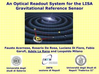
An Optical Readout System for the LISA Gravitational Reference Sensor. Fausto Acernese, Rosario De Rosa, Luciano Di Fiore, Fabio Garufi, Adele La Rana and Leopoldo Milano. Università degli Studi di Napoli "Federico II". INFN sezione di Napoli. Università degli studi di Salerno. LISA

An Optical Readout System for the LISA Gravitational Reference Sensor
E N D
Presentation Transcript
An Optical Readout System for the LISA Gravitational Reference Sensor Fausto Acernese, Rosario De Rosa, Luciano Di Fiore, Fabio Garufi, Adele La Rana and Leopoldo Milano Università degli Studi di Napoli "Federico II" INFN sezione di Napoli Università degli studi di Salerno
LISA (Laser Interferometer Space Antenna) • ESA-NASA collaboration: • Three spacecrafts in a equilateral triangle formation 5 milion km sidelength • Heliocentric orbit, following the Earth • Each spacecraft contains 2 test masses in geodesic motion
10-18 10-20 10-19 h 10-21 Detection threshold (S/N = 5) for a 1-year observation 10-22 10-4 10-1 100 10-23 Binary confusion limit 10-3 10-2 Frequency (Hz) LISA Sensitivity Curve Frequency range:0.1 mHz < f < 0.1 Hz RXJ1914.4+2456 401820-30 LISA sensitivity depends on the ability to set the test masses in free fall!
Lisa spacecraft layout • Some Fundamental issues: • Free fall of test masses • Spacecraft stationary around test masses • Gravitational Reference Sensor (GRS) control loop. A capacitive sensor drives microthrusters. Test masses • Because of the 60° angle between the test masses, to rectify the relative position of test masses and spacecraft we need: • Microthrusters driven by capacitve sensor to move the spacecraft along the main axis of the interferometer • Electrostatic actuation to move the test masses along the direction ortogonal to the main axis
Lisa spacecraft layout • Some Fundamental issues: • Free fall of test masses • Spacecraft stationary around test masses • Gravitational Reference Sensor (GRS) control loop. A capacitive sensor drives microthrusters. Electrode housing + test mass • Because of the 60° angle between the test masses, to rectify the relative position of test masses and spacecraft we need: • Microthrusters driven by capacitve sensor to move the spacecraft along the main axis of the interferometer • Electrostatic actuation to move the test masses along the direction ortogonal to the main axis
Translational DOFs Reference solution: Capacitive Sensor • First Plate: surface of the test mass. Second Plate: connected to the spacecraft. • Sensitivity requirements
Rotational DOFs Reference solution: Capacitive Sensor • Sensitivity requirements • It will be tested in the technology demonstration mission LISA Pathfinder. Is there a possible alternative solution for the GRS?
Optical readout system for the GRS of LISA • Goal: • Integration of the optical readout in the present design of the GRS. • Why an optical readout? • Risk reduction: back-up readout in case the capacitive one fails after the launch. • Redundancy: an independent readout provides extra information on couplings etc.. • Sensitivity: an optical readout is potentially more sensitive for some DOF. • A smaller noise level can relax the requirements on the cross couplings of noise in the other DOFs along the main axis!
Optical readout system for the inertial sensor of LISA • The drag free control loop should not spoil the position noise on the main interferometer axis X (4´10-11 m/Hz 1/2). • In the present LISA baseline, the position of the test mass along the main interferometer axis X is read interferometrically, while the transverse DOFs (Y and Z) are read by the capacitive sensor. • Assuming the sensitivity of the capacitive sensor (2´10-9 m/Hz1/2) for the Y and Z axes, taking into account that there are two proof masses per arm and putting some safety factor, we get a very strict requirement (~ 10-3) for the maximum coupling of noise in the transverse DOFs to the main axis. • Any improvement in sensitivity for the transverse DOFs turns out in a corresponding relaxation of the requirements on cross couplings.
Our proposal for the optical read-out • Optical lever: • laser beam sent to the test mass through a SM optical fiber • position of the reflected beam measured by a position sensor (QPD or PSD). • Advantages: simplicity, robustness. • The sensitivity depends on input power and measurement range (beam size for QPD or detector size for PSD). Test mass QPD Laser Optical fiber With a suitable combination of three beams and sensors we can recover the six DOF of the test mass.
Translational DOFs Capacitive sensor requirement El.+Sh. noise ORO Electronic noise ORO Shot noise ORO Potential sensitivity for the ORO Total Power: 0.2 mW Spot size: 0.4 mm Wavelength: l=633 nm
Requirements for the ORO • Back action, due to the radiation pressure of the light beam hitting the test mass: • F = radiation pressure • P = power of the laser beam • Compatibility with the present LISA design
Work in progress in Napoli • Characterization of the sensitivity of our ORO • Many different setups to improve the sensitivity and reduce the position sensor noise. • Integration of the ORO in LISA • Real scale prototype. • Test of the ORO on Trento Torsion pendulum • Test of the sensitivity and of the back action in conditions as near as possible to the free fall.
Rigid set up for the study of the sensitivity • Bench: single block of stainless-steel with interfaces for fiber couplers and sensors. • The system is symmetric for differential measurements. • The "test mass" can be moved for calibration. • The whole set-up is closed in a box to prevent effects due to air flows etc.
Sensitivity to the translational DOFs 1/f 1/f1/2 Total Power = 0.18 mW Spot size = 0.4 mm l= 633 nm beam path = 110 mm
The electrode housing and the ORO prototype 3 Fiber couplers 3 Position sensors • LISA Test-flight Package (LTP) model for the electrode housing • Small spaces for ORO and light ray trajectories • ORO realization has to take into account the overall dimensions of the electrode housing and the caging mechanism
The electrode housing and the ORO prototype Simplified figure Electrode Mirrors Z Y X Electrode Mirrors In the z and x trajectories of the beam the electrodes work as mirrors, reflecting light back to the test mass.
Protoype design compatible with LTP electrode housing project Lz Sz 2bz Top View Ly d 2by 2bx Sx Lxproj • Goals: • Experimental test of the correct passing of the light beams through the overall dimensions of the electrode housing. Not a test of sensitivity. • Study of the optical matrix. Front View
Fiber couplers PSD Z Signals: Zh , Zv z x y PSD X Signals: Xh , Xv PSD Y Signals: Yh , Yv Our real scale prototype Note: here we are using psd and not qpd
A detail of the prototype: angled connections of the ferrulae of the optical fibers Front view of the prototype
f Z q Y X h Working on the prototype • The light beams come out correctly, after making few adjustments with thin steel layers (~100 mm). • We calculated the analytical matrix of the system and we compared it with the measured experimental one. Vector of the photodiode signals Degrees of freedom of the test mass
Matrix of the system • B allows to calculate the position of the test mass once you know the signals from the photodiodes. • We can measure the matrix elements of the inverse matrix of B: • We can calculate A analitically, the matrix elements depending only on the geometry of the system.
The analytical matrix ATh The measured matrix AEx
Noise level in the reconstruction of the test mass motion in 6 DOFs • The noise level measured using the rigid set up considered so far refers to the displacement noise of a single beam on the detector. • In order to evaluate the noise level in the reconstruction of the test mass motion in 6 DOF, we must take into account: Matrix ATH • the geometry of the ORO • the linear combination of the signals read by the photodiodes.
Expected noise for each degree of freedom: Assuming the three QPDs being affected by the same noise level δXn: By using the measurement of the lowest noise level obtained with the rigid set up, we get the expected noise for each degree of freedom of our prototype. Note: We assume that the X, h and j are read interferometrically with negligible noise, while Y, Z and q are given by the ORO with the geometry of our prototype. Noise level in the reconstruction of the test mass motion in 6 DOFs
Sensitivity curves of the translational DOFs of the test mass related to the protoype’s geometry Ymeas Zmeas Capacitive sensor Ymodel Zmodel The noise on Y is higher than the other two because of the small angle of the Y beam.
Sensitivity curves of the rotational DOFs of the test mass related to the protoype’s geometry Capacitive sensor q The measured noise level is already good enough.
Optical sensor f 3 • Four masses pendulum • Single “soft” DOF: f rotations x»bf translations, free fall • Capacitive sensor on mass 1 • Optical sensor on mass 2 2 1 z 4 x Capacitive sensor y Next steps: testing the prototype on the torsion pendulum in Trento Images kindly granted by the LISA team in Trento.
f z h q y x Next steps: testing the prototype on the torsion pendulum in Trento Fiber coupler QPD Mass 2 Side view Fiber coupler QPD Shaft In this configuration the ORO is sensitive to x translations and to rotations h and f around z and y axis.
Conclusions : • About the sensitivity… • The measured ORO sensitivity for the single beam is better than the capacitive sensor sensitivity for f > 1mHz. • The measured noise level is a factor 3-5 higher than the model noise (shot + electronic noise). Further improvements looks feasible. About the integration in LISA… • The integration of a 6 DOF system in the present design of the GRS (the one on LTP) looks feasible and has been verified in a real scale bench top prototype. • Usage of an optical readout would relax considerably the specifications on cross couplings. • Angular noise level is already good enough. • For the LISA GRS we should be able to find a beam geometry enabling to extract the Z and Y DOFs of the test mass with a sensitivity between 1 and 0.1 nm/Hz1/2. Next steps:
Thank you for your attention! Any questions?