Download
1 / 25
250 likes | 413 Vues
Accumulation Process and Phenomena in Chamber Lift Completions. Sergio Caicedo. ASME/API Gas-Lift Workshop Houston, Texas, Spring 2002. OUTLINE Introduction Two-packer Chamber Equations Insert Chamber Equations Algorithm Results Conclusions Recommendations. INTRODUCTION.

E N D
Accumulation Process and Phenomena in Chamber Lift Completions Sergio Caicedo ASME/API Gas-Lift Workshop Houston, Texas, Spring 2002
OUTLINE • Introduction • Two-packer Chamber Equations • Insert Chamber Equations • Algorithm • Results • Conclusions • Recommendations
INTRODUCTION Chamber Lift Application Window Particularly suitable for wells with very low reservoir pressure, high productivity Chamber Lift Design Goal Accumulate more liquid volume per bottom hole flowing pressure Chamber Lift Main Problem Formation Gas in the chamber
INTRODUCTION • Production Cycle • Accumulation Stage • Liquid Accumulation In Annulus and Tubing • Formation Gas Accumulation in Annulus • Described by Gas and Liquid balance coupled with • Reservoir inflow • Chamber Displacement • Slug Lifting • Venting
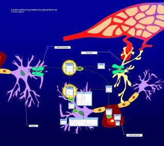
TWO-PACKER CHAMBER EQUATIONS TWO-PACKER CHAMBER COMPLETION
Ptop Yperf Operating Valve mgout Bleeding Valve Panu Ypinf Ytop Yanu amgres Standing Valve TWO-PACKER CHAMBER EQUATIONS Gas Balance in the annulus Liquid Balance Pressure relationship
Ptop Yperf Operating Valve mgout Bleeding Valve Panu Ypinf Ytop Yanu amgres Standing Valve TWO-PACKER CHAMBER EQUATIONS 2x2 System of Non Linear Differential equations !!!
Ptop Yperf Operating Valve mgout Bleeding Valve Panu Ypinf Ytop Yanu amgres Standing Valve TWO-PACKER CHAMBER EQUATIONS Reservoir Inflow Bottom Hole Flowing Pressure Gas rate through the Bleeding Valve
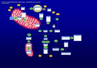
INSERT CHAMBER EQUATIONS INSERT CHAMBER COMPLETION
Ptop Yperf Operating Valve m1gout Bleeding Valves Panu1 m2gout Panu2 Ypinf Ytop Yanu1 a2mgres Yanu2 a1(1-a2)mgres Standing Valve INSERT CHAMBER EQUATIONS Gas Balance in the external annulus Gas Balance in the internal annulus Liquid Balance
Ptop Yperf Operating Valve m1gout Bleeding Valves Panu1 m2gout Panu2 Ypinf Ytop Yanu1 a2mgres Yanu2 a1(1-a2)mgres Standing Valve INSERT CHAMBER EQUATIONS Gas rate through the Bleeding Valves
INITIAL AND BOUNDARY CONDITIONS The key to simulate the accumulation process in both cases is to introduce the proper initial conditions and suitable boundary or limit conditions. For instance, the initial level in the annulus is zero because all the liquid has been displaced during the previous injection stage, meanwhile the initial liquid level depends on the fall back of the slug in the previous production cycle. Among the limit conditions, the limit when the liquid level in the annulus approaches zero requires special care in order to keep the system consistent.
Annular & Tubing Liquid Levels vs. Accumulation Time Column (ft) Accumulation Time (s) RESULTS --Annulus -- Tubing Liquid Levels vs. Time for a 100-feet two-packer chamber with a 3/16" bleeding port and 10% of gas coming into the annulus
RESULTS Annular & Tubing Liquid Levels vs. Accumulation Time --Annulus -- Tubing Column (ft) Accumulation Time (s) Liquid Levels vs. Time for a 100-feet two-packer chamber with a 1/32” bleeding port and 10% of gas coming into the annulus.
Annular & Tubing Liquid Levels vs. Accumulation Time Column (ft) Accumulation Time (s) RESULTS --Annulus -- Tubing . Liquid Levels vs. Time for a 100-feet two-packer chamber with a 3/16” bleeding port and 50% of gas coming into the annulus.
RESULTS Annular & Tubing Liquid Levels vs. Accumulation Time --Annulus1 -- Annulus2 -- Tubing Column (ft) Accumulation Time (s) Liquid Levels vs. Time for a 200-feet Insert Chamber with a 3/16” internal and external bleeding ports.
RESULTS Annular & Tubing Liquid Levels vs. Accumulation Time --Annulus1 -- Annulus2 -- Tubing Column (ft) Accumulation Time (s) • Liquid Levels vs. Time for a 200-feet Insert Chamber with a 3/16” internal and a 1” external bleeding ports
Annular & Tubing Liquid Levels vs. Accumulation Time Column (ft) Accumulation Time (s) RESULTS --Annulus1 -- Annulus2 -- Tubing Liquid Levels vs. Time for a 200-feet Insert Chamber with 1" internal and external bleeding ports
Ptop Yperf Operating Valve m1gout Bleeding Valves Panu1 Panu2 m2gout Ypinf Ytop a2mgres Yanu1 Yanu2 a1(1-a2)mgres Standing Valve RESULTS Insert Chamber Improvement
Annular & Tubing Liquid Levels vs. Accumulation Time Column (ft) Accumulation Time (s) RESULTS --Annulus1 -- Annulus2 -- Tubing Liquid Levels vs. Time for a 200-feet Insert Chamber with a 3/16" internal and a 1/2" external bleeding ports
CONCLUSIONS The complexity of the accumulation process in chamber lift requires the previous analysis for a better sizing of the bleeding valves. The coherence and physical behavior of the results along with the field experiences backups the theoretical model and the numerical method. The slight differences between the two-packer and insert chambers completions do not allow applying the same practices in both installations.
RECOMMENDATIONS In insert chamber completions it is highly recommended to connect directly the external annulus with the tubing whether it is possible. Apply the model developed in this paper when designing or simulating wells with two-packer or insert chamber lift installations. Start a research work in order to determine the gas percentages of separation that flow into the annulus and tubing in chamber lift installations in order to include that key information in the presented model.
QUESTIONS ??? FEEL FREE PLEASE