Download
1 / 42
420 likes | 448 Vues
Learn about the construction and performance of Gas Electron Multiplier detectors in nuclear contraband detection using Muon Tomography. The detectors interact with charged particles and photons, featuring a GEM configuration with high-Z materials. Detailed steps include testing, framing, stretching, gluing, and assembling the detectors for optimal performance. Enhance your understanding of atomic photoelectric effects and multiple Coulomb scattering for efficient detection.

E N D
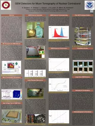
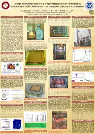
Construction and performance of Gas Electron Multiplier detectors for nuclear contraband detection using Muon Tomography Amilkar Quintero Advisor: Dr. Marcus Hohlmann June 18, 2010
Interaction of charged particles with matter The variation of the energy loss around the mean energy loss value is an asymmetric distribution called the Landau distribution The area density of the medium
Interaction of Photons with matter The atomic photoelectric effect is very important for gaseous detectors development, since X-rays isotopes (~keV) are commonly used to test these detectors.
Photoelectric Effect Incoming photons Detector Ion Nucleus Secondary Ionization Primary Ionization Electron Readout
Multiple Coulomb Scattering Cosmic ray Atmosphere molecule Particles 2 Detectors High-Z material 2 Detectors Scattering angle
Gas Electron Multiplier • Foil of Kapton coated with copper layers on both sides and chemically pierced. • High voltage is applied across GEM foils so high electric field makes an avalanche of electrons through the holes . • Gas mixture of Argon and CO2 in the volume proportion 70-30. • Spatial resolution ~50mm. • Triple-GEM configuration allows foils to hold lower voltage. • Two dimension readout.
GEM features Our GEM detectors are based on TERA Foundation detectors design which are an upgraded version of the 30 cm x 30 cm COMPASS experiment GEM detectors. We made minor improvements on the TERA GEM design, notably on the design of frame that support the GEM foils and define space between different GEM foils. Each GEM foil is divided in 12 sectors in order to reduce the discharge probability and its spread over the entire area. Courtesy of COMPASS
GEM foils testing Validation condition: 500 volts with leakage current less than 5 nA, in Nitrogen (operational voltage ~300 V) Test performed in class 1000 clean room. Nitrogen should flow at least five box volumes. Test is made before and after framing 24 foils were framed. Before Framing After Framing Average 2 nA Average 1.3 nA
Frames Honeycomb Drift cathode Frame GEM 1 Frame GEM 2 Frame GEM 3 Frame Readout Honeycomb
Frames Preparation The frames have been re-designed to reach maximum performance with thermal method for stretching and gluing the foils. The new design also facilitate the alignment of all framed foils during assembly procedure. Inner strips are to maintain the distance between foils. Coat the inner parts and put the frames in the oven per 12 hours at a temperature of 45 0C.
Stretching the foils We use the thermal method to stretch the foils. We designed the stretching device for 30cm 30cm foils. Put it in the oven at 45 0C, in ~20 minutes should be stretched. We are the first group to use the thermal method for 30cm 30cm foils.
Gluing frames Glue the frame onto the stretched foil, still in the stretching device, and put them in the oven at 45 0C for 12 hours for the glue to polymerize. Framed foils are re-tested with high voltage. GEM 3 must have an slit for the gas system.
Drift cathode Honeycomb Drift cathode Frame GEM 1 Frame GEM 2 Frame GEM 3 Frame Readout Honeycomb
Drift cathode The drift cathode is made of a 5 mm copper on 50 mm Kapton foil Honeycomb structure glued onto the Kapton side as support for mechanical rigidity. Air bubbles must be removed.
Spacer for drift region A 3 mm frame is glued onto the drift cathode on the copper side that define the drift region of the detector. The extend strip of the cathode is where the HV is applied
Readout Honeycomb Drift cathode Frame GEM 1 Frame GEM 2 Frame GEM 3 Frame Readout Honeycomb
Readout The two-dimensional readout consists of two layers of perpendicular copper strips at 400 mm pitch separated by 50 mm. Like for the drift cathode, we glue the readout board on a honeycomb structure support. Courtesy of D. Watts TERA Foundation
Assembly Honeycomb Drift cathode Frame GEM 1 Frame GEM 2 Frame GEM 3 Frame Readout Honeycomb
Stack the detector We glue together the drift cathode and the 3 framed GEM foils (12 hours for polymerization of the glue). Remove the extra material part
Final step in clean room Glue the stacked foils on to the readout board. First two detectors of June 2009
Coating the detectors We coat the side of the assembled detectors to prevent gas leaks and guarantee a good gas tightness
High Voltage Board The HV board is a voltage divider with 3x12 inputs to equally and independently apply HV to each of the 12 sectors of the 3 GEM foils of one triple GEM detector. The bias current is tested before and after the HV board is attached to the detector to validate its Ohmic behavior (equivalent resistance of 5.42 M). Disconnected Connected
Gas System Gas Inlet Slits Grooves in drift spacer Gas Outlet HV board
Argon escape Gate pulse of ADC Photo peak Commissioning - X-rays 1. Readout strips for one sector are ganged together to study the entire area, the others sectors are grounded. 2. Mounted Triple-GEM detector for X-ray source test at GDD lab at CERN. 3. Energy spectrum obtained with 8.04 keV Cu X-ray , showing a ~ 20% energy resolution (FWHM) (Gaussian fit in blue).
Commissioning - Cosmic rays Around 100,000 muon events were recorded using one sector of the total active area (30cm 5cm) for five hours. We expect ~45,000 counts at sea level, but since Geneva is at 373 m above sea level, more cosmic ray particles are detected.
Rate and Charge Sharing The rate of counted X-rays 41.03 kHz at plateau at 3.9 kV Charge sharing factor kc=1.2228
Gain The current is measured directly from the readout COMPASS Result Average energy to produce ion-electron pair
Drift Cathode FR 4 frame Spacers Readout Small GEM Detector Aluminized Mylar lid
Results HV test Disconnected from the detector Connected to the detector Previous result: y = 5.4337x – 17.884
Commissioning - Cosmic Area 10cm 5cm Rate 40 cpm (50 cpm theoretical value) Applied voltage 4.3 kV
Commissioning – 55Fe Area 10cm 5cm Resolution ~60 % (FWHM) Applied voltage 4.3 kV
Performance - Rate • Source 55Fe (5.9 keV) • Plateau 4.05 kV Possible causes: gas mixture, holes shape, bad electric field, energy of the source.
Calibration Input signal : -Width: 0.1 ms -Height: 0.1 V to 1.5 V Eq. II The Pre amplifier is an integrator with a 1 pF capacitor
Gain of small detector Eq. I = Eq. II => Qcal
Gain with different calibration pulse Width (ms)
4 1 16 14 Uniformity Average: 0.4274 Vms Standard Deviation: 0.0237 Vms
Honeycomb FR 4 frame GEM foil Readout Honeycomb Detector Honeycomb lid Area 10cm 5cm Rate 20 cpm (50 cpm theoretical value) Applied voltage 4.3 kV Noise level 0.9 V Very sensitive to vibration
Summarize and Conclusion • Assembled 7 detectors, 30cm 30cm active area. Only one shows problems. • Assembly time of one detector is 4 days. • Cosmic rays and Cu X-rays (energy resolution ~20% FWHM) spectrums are reproduced. • Rate plateau shows at 3.9 kV. • Gain ~2 104. • Standard small detector reproduces cosmic rays and 55Fe X-rays spectrums (energy resolution ~60% FWHM). • The displacement in the plateau of the small detector modify the results obtained with the big chambers. • Honeycomb detector reproduce the cosmic rays distribution but it is very sensitive to vibration.
Appendix A Iron 55 decay: 55Fe + e- 55Mn + e Electron capture 5.9 keV 55Mn 55Fe K-shell K-shell