Download
1 / 19
190 likes | 209 Vues
This study aims to accurately characterize the spurious signal propagation through the packaging hierarchy to the die, by tackling the complexity of electromagnetic interactions and abstracting it. It involves a hierarchical modeling approach and systematic order reduction of numerical models.

E N D
Modeling and Simulation of Conducted and Radiated EMI from HPM and UWB Sources on Printed Circuit Boards and Integrated Circuits A. C. Cangellaris and E. Michielssen ECE Department University of Illinois at Urbana-Champaign D. Yang EECS Department University of Illinois at Chicago
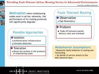
EMI to connectors & packages Antennas Cracks Apertures Cables Circuits Internal Coupling Propagation to interior HPM/UWB Sources Internal fields as radiated EMI Spurious behavior Objective • Characterize accurately the spurious signal (noise) propagation through the packaging hierarchy (printed circuit boards, cards, connectors, interposer, package…) to the die.
Successful fulfillment of this objective is dependent on our ability to tackle the EM complexity and abstract it • EM Complexity • Geometric complexity and distributed nature of the packaging hierarchy (“coupling path”) • Broad frequency bandwidth of the interfering signal • Non-linearity of the terminations • Tackling Complexity • Hierarchical approach to the modeling of electromagnetic interactions • From lumped models to transmission-line models to full-wave models • Abstracting Complexity • Systematic order reduction of numerical models of the coupling path • Equivalent circuit representation of the coupling path for its seamless incorporation in network-oriented non-linear circuit simulation
Radiated EMI Virtual coupling ports Integrating Substrate (PCB, MCM, …) Conducted & radiated EMI Packaged digital & analog devices Physical coupling ports (e.g., connectors, cables…) V V From the physical structure to the network representation of the EMI effect EM Modeling & Simulation Model Order Reduction Synthesis Equivalent source representation of radiated EMI coupling Source representation of conducted noise at the physical ports Network representation of the coupling path Non-linear lumped circuits
Specific subtasks • Task 1. Development of a coupling path modeling methodology • Task 2. Development of a (EMI) source modeling methodology • Task 3. Non-linear Transient Simulation of the hybrid lumped-distributed non-linear network
MTL Y(s) MTL Y(s) MTL MTL Y(s) Integrating Substrate (e.g. PCB) Task 1. Modeling of the Coupling Path • Our modeling approach is hierarchical • Domain decomposition • Use suitable EM modeling approach for individual blocks • Multi-conductor Transmission Lines (MTL) • Full-wave modeling (FEM, integral equation). Use fast frequency- and time-domain solvers from Task 1
Vector Fitting Task 1. Modeling of the Coupling Path • For each individual block develop a frequency-dependent multi-port representation in terms of a matrix transfer (e.g. admittance) function • Directly, through model order reduction • SVD-based & Krylov methods • Indirectly, from the discrete time or frequency responses The Indirect Approach:
Task 1. Modeling of the Coupling Path • Curve fitting constrained to produce stable representations • Subsequent post-processing to render the representation passive • Foster canonical representations of passive, reciprocal, linear multi-ports of finite order lead to strictly passive equivalent circuit synthesis • Direct compatibility with general-purpose, non-linear, network analysis-oriented circuit simulators
Example Study: SPICE-based transient simulation of switching noise in digital systems • Objective: Through simulation select appropriate decoupling capacitors to control voltage reference disturbances during switching • Modeling & Simulation Strategy • EM modeling of the power distribution network • Synthesis of SPICE-compatible equivalent circuit • SPICE-based transient simulation EM modeling of power & ground plane pair Circuit models for voltage regulator and switching driver
Example Study: SPICE-based transient simulation of switching noise in digital systems Step 3:Equivalent Circuit synthesis
Synthesized equivalent circuit Circuit models for voltage regulator and switching driver Example Study: SPICE-based transient simulation of switching noise in digital systems Decoupling capacitor Supply voltage disturbance suppressed due to the presence decoupling capacitor Supply voltage disturbance without decoupling capacitor
Task 2. Modeling of the (EMI) Source • Radiated EMI most challenging • Procedure: Given the excitation and the physical description of the coupling path, calculated the induced currents at the short-circuited ports where non-linear circuitry is connected • Once again, our approach is hierarchical • When valid, use known EM field to MTL coupling models • Extensive use of UIUC PWTD fast solver • Deterministic approach of limited use • Develop statistics for the attributes of the induced current waveforms
NA 30 cm 20 cm 2mm Example Study: EMI of a Stacked-Card Configuration Objective Geometry Compute common mode current on the coax cable Discretization • Excitation fmax = 1 GHz • at fmax = 0.3 m, ds at fmax = /300 /10 • use Adaptive LF-PWTD (ALF-PWTD)
Example Study: EMI of a Stacked-Card Configuration Comparison of computed |S21| to the measured result* * www.emcs.org/tc9
Task 3. Non-Linear Transient Simulation • Two Approaches: • Physics-oriented Non-linear Transient Simulation • Physical (distributed) model for the coupling path • Circuit models for non-linear electronics • Most rigorous and exact; yet, computationally intensive (small-scale applications) • UIUC’s Fast PWTD Solver is the work horse • Interfacing with non-linear circuit solver with models for the semiconductor devices • “Standard” SPICE not the optimal choice because its architecture is biased by applications involving, lumped (primarily RC) passive circuitry
Example Study: A Hybrid Cross-talk/EMI problem(TC9 Challenge Problem) Geometry mesh 15 cm Point 1 (Excitation) Point 2 Point 4 Point 3 80 cm Discretization • Excitation fmax = 3 GHz • at fmax = 0.1 m • ds at fmax = /500 /8
Example Study: A Hybrid Cross-talk/EMI problemVoltage responses (comparison with PEEC solver) Excitation Pulse Voltage at Load Point 2 Voltage at the left wire Voltage at the upper wire
Task 3. Non-linear Transient Simulation • Network-oriented Non-linear Transient Simulation • In the spirit of traditional SPICE; however, enhanced with capabilities relevant to the primarily distributed RLC nature of the passive circuitry • Better convergence than “standard” SPICE • Versatility in the “black-box” representation of blocks of the coupling path • TRANSIM is such a simulator • Under development at North Carolina State University (NCSU) in Prof. M. B. Steer’s group • On-going enhancement of its EM modeling capabilities through a collaborative effort between UIUC (A. Cangellaris) and NCSU • In addition to its use as the primary engine of the network-oriented non-linear transient simulation, TRANSIM will be interfaced with the fast solver PWTD
Summary • The objective is to characterize through modeling and simulation the EMI signals propagating through the packaging hierarchy to the digital/analog circuitry • To accomplish this, the following subtasks will be undertaken: • Modeling of the coupling path and its reduction into an equivalent network representation • Modeling of the (EMI) sources • Development of a robust and versatile non-linear transient simulation environment that combines SPICE-like lumped-circuit simulation capability with distributed-circuit simulation capability