1 mm
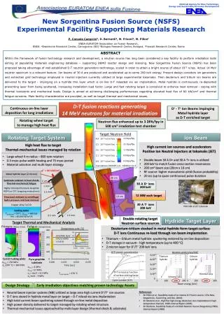
National Agency for New Technology, Energy and Sustainable Economic Development. New Sorgentina Fusion Source (NSFS) Experimental Facility Supporting Materials Research P. Console Camprini a , D. Bernardi a , M. Frisoni b , M. Pillon c ENEA-EURATOM Association on Fusion Research ,

1 mm
E N D
Presentation Transcript
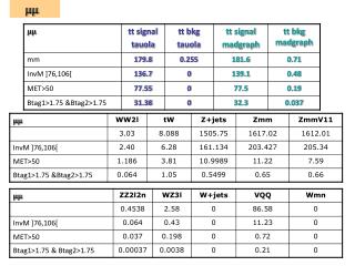
National Agency for New Technology, Energy and SustainableEconomic Development New Sorgentina Fusion Source (NSFS) ExperimentalFacilitySupportingMaterialsResearch P. Console Camprinia, D. Bernardia, M. Frisonib, M. Pillonc ENEA-EURATOM Association on Fusion Research, ENEA: aBrasimoneResearch Center, Camugnano (BO) bBolognaResearch Center, Bologna, cFrascatiResearch Center, Rome ABSTRACT Within the framework of fusion technologyresearch and development, a neutron source has long beenconsidered a keyfacility to performirradiationtestsaimingatpopulatingmaterialsengineering database – supporting DEMO reactor design and licensing. New Sorgentina Fusion Source (NSFS) hasbeenproposedtakingadvantage of well-established D-T neutrongeneratorstechnology, scaled in order to attain a bright source of about 1015 n/sec. Actual 14 MeVneutronspectrumis a relevantfeature. Ionbeams of 30 A are produced and accelerated up to some 200 keVenergy. Present design considersiongenerators and extractiongridtechnologyemployed in neutralinjectorscurrentlyutilizedat large experimentaltokamaks. Thendeuterium and tritiumionbeams are delivered to the target - impinging on a hydridethinlayerwhichis on-line D-T reloaded via ionimplantation. Metal hydrideiscontinuously re-depositedpreventinglayer from beingsputtered, increasinginstallationloadfactor. Large and fast rotating target isconceived to enhanceheatremoval - coping with thermaltransients and mechanicalloads. Design isaimedatachievingchallenging performances regardingelevatedheatflux of 60 kW/cm2 and thermalfatigueconcerns. Mainfacilitycharacteristics are provided, aswellas target thermal and mechanicalissues. D-T fusion reactionsgenerating 14 MeVneutrons for materialirradiation Continuous on-line layerdeposition for long irradiations D+ - T+IonBeamsImpinging Metal hydridelayer asD-T enrichedtarget Rotatingwheel target to manage high heatflux Neutronfluxenhanced up to 3 DPA/fpy in 500 cm3irradiationtest chamber Rotating Target System Ion Beam • High heatflux to target • Thermal-mechanicalissuesmanaged by rotation • High currentionsources and accelerators • Positive IonNeutralInjectorsattokamaks(JET) Target NeutronYield 3.0dpa/fpy 2.1 dpa/fpy 1.3 dpa/fpy 0.8 dpa/fpy 0.6 dpa/fpy 4.0 10 13 n/cm2/sec 2.5 10 13 n/cm2/sec 1.6 10 13 n/cm2/sec 1.1 10 13 n/cm2/sec 6.8 10 12 n/cm2/sec • Large wheel 4 m radius – 800 rpmrotation • 0.3 msecpulse-widthheating and 75 msecperiod • Materialselection and multi-layerstrategy • Double beam 30 A D+ and 30 A T+ ionsisutilized • 200 keV to match fusion cross-sectionresonances • 200 cm2beamsize (20cm x 10 cm) • RF source: highermonoatomicyield(fusion probability) • 20 sec (up to quasi-continuous) pulseduration Calculations MCNP5-1.6 - FENDL3-rel.4 q’’ = 60 kW/cm2 • Metal hydridelayer (2 micron) 20 cm • Susbtrateresistant to heat shocks • Thermal-mechanicalfatigue • Highly OrientedPyrolyticGraphite • HOPG or CFC (ongoingevaluations) 2 m 30 A D+ ions 200 keV 1 mm 1.5 mm 12 MW each target 10 cm • Structuralresistant to centrifugalhydro pressure and heatremoval • CopperalloyCuCrZr 30 A T+ ions 200 keV 2 mm PINI NBI at JET tokamak • Cooling water • Tbulk(inlet) = 50°C , p(top) = 660 bar • Htc = 60,000 W/m2/K 1.5 mm 0.5 mm Double rotating target Neutronsurfacesources Hydride Target Layer Target Thermal and Mechanical Analysis Primary: Mises Stress Fatigue: temperature Deuterium-tritiumstocked in metal hydrideform target surface D-T ionsContinuous re-loadthroughionbeamimplantation Temperature cycle [°C] • Titanium – Erbiummetal hydride: sputteringrestored by on-line deposition • D-T storage in vacuum- high temperature (up to 400 °C) • 2 micron layer for D+/T+ 200 keVions D/Ti atomic concentration Neutron yield [n/sec/kW] 5x10¹¹ Titanium hydride Erbium hydride CuCrZrtubingplate Pyro-graphitesubstrate 4x10¹¹ σmax = 230 MPa σy (100 °C) ≈ 380 MPa 3x10¹¹ Time [sec] σmin = 4 MPa σmax =17 MPa σa = Δσ/2 = 6.5 MPa σalimit̴ 9 MPa 2x10¹¹ D-T re-load as function of surface sticking factor Tmaxhydride = 370 °C 1x10¹¹ H/metal ratio H/metal ratio 0 Cycle number (104) 300 0 100 200 300 0 100 200 Beam energy [keV] Design Strategy EarlyirradiationobjectivesmatchingproventechnologyAssets • References • M. Pillon et al., Feasibilitystudy of an intense D-T fusion source: «The New Sorgentina», Fusion Eng. and Des. (2014) • M. Martone et al., High flux high energydeuteriumionsimplantation in high temperature titanium, ENEA Internal Report (1992) • M. Martone, FeasibilityStudy of a 14 MeVNeutron Source (Sorgentina), ENEA Internal Report (1990) • Neutralbeaminjectorsystems (NBI) utilizedas large area high current D+/T+ ionsources • D-T ionsstored in hydride metal layer on target – D-T reload via ionsimplantation • High totalcurrentbeamsputteringsolvedthrough on-line metal deposition • High powerdensitydelivered to target managed by rotatingwheelstructure • Thermal-mechanicalissuesapproached by multi-layer design (thermal shock & substrate)