Weld Joint Geometry and Welding Symbols
290 likes | 2.59k Vues
Weld Joint Geometry and Welding Symbols. Basic Weld Joints Welding Technology LEE CO. ATC Graphics compliments of AWS. Submitted by Craig Herald Welding Instructor Lee County Area Technology Center. To the AWS Welding Educator’s Electronic File Library www.aws.org/Educators.

Weld Joint Geometry and Welding Symbols
E N D
Presentation Transcript
Weld Joint Geometry andWelding Symbols Basic Weld Joints Welding Technology LEE CO. ATC Graphics compliments of AWS
Submitted by Craig Herald Welding Instructor Lee County Area Technology Center To the AWS Welding Educator’s Electronic File Library www.aws.org/Educators Graphics provided compliments of the American Welding Society Education Department
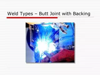
Five Basic Welded Joints Butt Joint Butt joint- a joint between two members aligned approximately in the same plane
Five Basic Welded Joints Corner Joint Corner joint - a joint between two members located at right angles to each other
Five Basic Welded Joints T-Joint T- joint - a joint between two members located approximately at right angles to each other in the form of a T
Five Basic Welded Joints Lap Joint Lap Joint- a joint between two overlapping members
Five Basic Welded Joints Edge Joint Edge joint- a joint between the edges of two or more parallel or nearly parallel members
Proper terminology is needed in everyday job communication • Joint design identifies, “the shape , dimensions, and configuration of the joint • The individual workpieces of a joint are called members. • Three types members nonbutting member, butting member , and splice member
A buttingmember is “a joint member that is prevented, by the other member from movement in one direction perpendicular to its thickness dimension” A nonbutting member is “a joint member that is free to move in any direction perpendicular to its thickness dimension
A splice member is “ the work piece that spans the joint in a spliced joint Single-spliced butt joint Double-spliced butt joint with joint filler