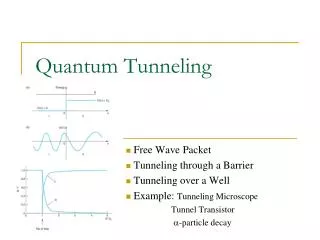
Tunneling Accelerometers
Tunneling Accelerometers. ME 381 Final Presentation December 6, 2004. Samantha Cruz Kevin Lee Deepak Ponnavolu. Introduction. High sensitivity Low range. Applications: Underwater acoustic detection. Seismology Micro-g measurements. Concept. Sensor Basics

Tunneling Accelerometers
E N D
Presentation Transcript
Tunneling Accelerometers ME 381 Final Presentation December 6, 2004 Samantha Cruz Kevin Lee Deepak Ponnavolu
Introduction High sensitivity Low range Applications: Underwater acoustic detection. Seismology Micro-g measurements.
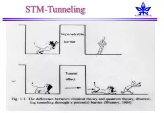
Concept Sensor Basics • On acceleration, the proof mass moves • This changes distance which changes tunneling current • Feedback circuit fights to maintain the same tunneling current by changing voltage of electrode • The force required to keep it at the same position is used to figure out acceleration
Microfabrication Counter-electrode cantilever (a) e- beam evaporation, (b) lithography and ion milling (c) ion milling (d) sacrificial layer (e) masking and metal evaporation (f) cantilever release
Microfabrication Tunneling electrode cantilever • e- beam evaporation • SiO2 deposition and etching • SOI • removal of back Si, tip mold etched • e- beam evaporation • mask and ion milling • cantilever release
Sensing • It = VB*exp(αI√Φ*xtg) Where VB = tunneling bias across electrode gap αI = 1.025(Å-1eV-0.5) Φ = height of tunneling barrier xtg = minimum tunneling gap It = tunneling current
Feedback Control Feedback Circuit • Operational Amplifier controls the tunneling Current • High Voltage supply is used to correct for change in deflection voltage for proper separation of the proof mass and tip drifts slowly over time
Noise Correction • Equivalent acceleration error √((4*kB*T*ωo)/(mp*Q)) Where, kB = Boltzmann constant T = Temperature ωo = Resonant frequency of proof mass mp = mass of proof mass Q = Mechanical quality factor
Conclusion • Amazing Sensitivity • Great range • High Bandwidth • ONLY FOR APPLICATIONS THAT REQUIRE HIGH SENSITIVITY