Download
1 / 28
310 likes | 534 Vues
Acoustic Emission Wave Propagation and Source Location. Dr. Boris Muravin. More at www.muravin.com. Outline. Introduction. Types of Acoustic Emission waves. Wave propagation modes. Wave propagation modes in various geometries and materials.

E N D
Acoustic Emission Wave Propagation and Source Location Dr. Boris Muravin More at www.muravin.com More about AE at www.muravin.com
Outline • Introduction. • Types of Acoustic Emission waves. • Wave propagation modes. • Wave propagation modes in various geometries and materials. • Wave propagation effects (attenuation, dispersion, scattering and other). • Group and phase velocity. • Dispersion curves. More about AE at www.muravin.com
Introduction • Acoustic Emission (AE) is a phenomenon of stress wave radiation caused by a dynamic reconstruction of material’s structure that accompanies processes of deformation and fracture. • Crack propagation is one of the macroscopic sources of AE. Cracks and other discontinuities in a material concentrate stresses. Crack jumps accompanied by a rapid release of potential energy, a small part of which is released in form of stress waves. • Stress waves are generated when the rate of the stress field change locally is such that the stresses cannot be instantaneously transmitted to the different areas of the body. More about AE at www.muravin.com
Types of Acoustic Emission Waves Type of AE waves generated depend on material properties, its mechanical behavior and level of stresses at the source. AE waves can be: • Elastic. • Non-linear elastic. • Elastic-plastic. • Elastic-viscoplastic and other. Anelastic waves attenuate at short distances and therefore elastic waves are mostly detected and analyzed in acoustic emission testing. More about AE at www.muravin.com
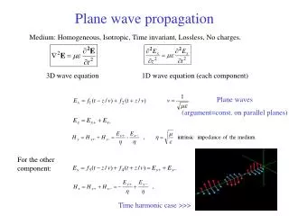
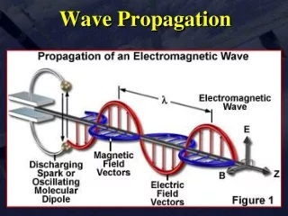
Modes of Elastic Waves Propagation • Longitudinal (dilatational, P-) wave is the wave in which the oscillations occurring in the direction of the wave propagation. • Shear (or transverse, or distortional, or equivolumal, S-) wave is the wave in which the oscillations occurring perpendicular to the direction of the wave propagation. • Rayleigh (or surface) wave is the wave with elliptic particle motion in planes normal to the surface and parallel to the direction of the wave propagation. • Lamb (or plate)wave is the wave with particles motion in perpendicular to the plate. • Stoneley (or interfacial) wave is the wave at interface between two semi-infinite media. • Love wave is the wave in a layered media, parallel to the plane layer and perpendicular to the wave propagation direction. • Creeping wave is the wave that is diffracted around the shadowed surface of a smooth obstacle. More about AE at www.muravin.com
Example of AE Signal More about AE at www.muravin.com
Longitudinal, Shear, Rayleigh and Love Waves Reference: http://web.ics.purdue.edu/~braile/edumod/slinky/slinky.htm More about AE at www.muravin.com
t = 10 mm t = 5 mm Wave Modes in Different Geometries • In infinite media there are only two types of waves: dilatational (P) and distortional (S). • Semi-infinite media there are also Rayleigh and Lateral (Head) waves. Head waves produced by interaction of longitudinal wave with free surface. • In double bounded media like plates there are also Lamb waves. Symmetric Antisymmetric In thinnest plates only Lamb wave arrivals are visible. More about AE at www.muravin.com
Wave Speed in Different Materials Wave speeds derivation: λ and μ – Lame constants ν – Poisson’s ratio ρ – material density More about AE at www.muravin.com
Properties of Elastic Waves in Semi-Infinite Media • Rayleigh waves carry 67% of total energy (for ν=0.25). • Shear 26%. • Longitudinal 7%. • Longitudinal and shear waves decay at a rate 1/r in the region away of the free surfaces. • Along the surface they decay faster, at a rate 1/r2. • Rayleigh waves decays much slower, at a rate of 1/sqrt(r). Reference: “Dynamic Behavior of Materials” by M. Meyers More about AE at www.muravin.com
Wave Propagation Effects The following phenomena take place as AE waves propagate along the structure: • Attenuation: The gradual decrease in AE amplitude due to energy loss mechanisms, from dispersion, diffraction or scattering. • Dispersion: A phenomenon caused by the frequency dependence of speed for waves. Sound waves are composed of different frequencies hence the speed of the wave differs for different frequency spectrums. • Diffraction: The spreading or bending of waves passing through an aperture or around the edge of a barrier. • Scattering: The dispersion, deflection of waves encountering a discontinuity in the material such as holes, sharp edges, cracks inclusions etc…. • Attenuation tests have to be performed on actual structures during their inspection. • The attenuation curves allow to estimate amplitude or energy of a signal at a given distance from a sensor. More about AE at www.muravin.com
Group and Phase Velocity Lord Rayleigh: “It have often been remarked that when a group of waves advances into still water, the velocity of the group is less than that of the individual waves of which it is composed; the waves appear to advance through the group, dying away as they approach its interior limit” (1945, Vol. I, p. 475). • Group velocity is the velocity of propagation of a group of waves of similar frequency. • Phase velocity is the velocity at which the phase of the wave propagates in the media. Reference: http://www.owrc.com/waves/waveSpeed/waveSpeed.html More about AE at www.muravin.com
Dispersion Curves Triple point Non-dispersive part of A0 mode Example calculated for steel 347 plate (10mm thick) More about AE at www.muravin.com
Use of Dispersion Curves Dispersion curves can be effectively used for accurate location and characterization of AE sources. Examples: • Filtering AE waveforms at frequency of the triple point (200 kHz), one can improve location accuracy. This is because all modes at this frequency have similar speed and the threshold will be triggered by the same wave mode at all sensors. • Filtering AE waveforms over non-dispersive range of A0 mode (80-180 kHz) can improve location accuracy even further. In this technique a wider frequency range of the original signal remain after filtration while the frequency content of the mode remain unchanged over the distance. More about AE at www.muravin.com
Principals of Acoustic Emission Source Location • Time difference based on Time of Arrival locations. • Cross-correlation time difference location. • Zone location. • Attenuation based locations. • Geodesic location. More about AE at www.muravin.com
Time of Arrival Evaluation • Most of existing location procedures require evaluation of time of arrival (TOA) of AE waves to sensors. • TOA can detected as the first threshold crossing by AE signal, or as a time of peak of AE signal or as a time of first motion. TOA can be evaluated for each wave mode separately. More about AE at www.muravin.com
Effective Velocity • Another parameter necessary for time difference location method is effective velocity. • Effective velocity can be established experimentally with or without considering different wave propagation modes. • When propagation modes are not separated, the error in evaluation of AE source location can be significant. For example, in linear location it can be about 10% of sensors spacing. • Detection of different wave modes arrival times separately and evaluation of their velocities can significantly improve location accuracy. Nevertheless, detection and separation of different wave modes is computationally expensive and inaccurate in case of complex geometries or under high and variable background noise conditions. • Another parameter necessary for time difference location method is effective velocity. • Effective velocity can be established experimentally with or without considering different wave propagation modes. • When propagation modes are not separated, the error in evaluation of AE source location can be significant. For example, in linear location it can be about 10% of sensors spacing. • Detection of different wave modes arrival times separately and evaluation of their velocities can significantly improve location accuracy. Nevertheless, detection and separation of different wave modes is computationally expensive and inaccurate in case of complex geometries or under high background noise conditions. More about AE at www.muravin.com
Linear Location • Linear location is a time difference method commonly used to locate AE source on linear structures such as pipes, tubes or rods. It is based on evaluation of time difference between arrival of AE waves to at least two sensors. • Source location is calculated based on time difference and effective wave velocity in the examined structure. Wave velocity usually experimentally evaluated by generating artificially AE at know distances from sensors. More about AE at www.muravin.com
One Sensor Linear Location • It is possible to use one sensor to evaluate the distance from AE source (but not direction). • The principal of this location is based on phenomenon of different velocity of propagation of different wave modes. • Such location method can be used on short rods, tubes or pipes, when mode detection and separation can be effectively performed. More about AE at www.muravin.com
R3 Two Dimensional Source Location For location of AE sources on a plane minimum three sensors are used. The source is situated on intersection of two hyperbolas calculated for the first and the second sensors detected AE signal and the first and the third sensor. Sensor 2 R2 R3 Sensor 3 Sensor 2 R2 R1 Z D Sensor 1 R1 Sensor 1 More about AE at www.muravin.com
Over-determined Source Location • Generally, it is necessary 2 sensors for linear, 3 sensors for 2D and 4 sensors for 3D locations. • When more sensors detect AE wave from a source than necessary it is possible to use this information to improve location accuracy by error minimization optimization methods. Chi Squared error function that minimized in over-determined source location. More about AE at www.muravin.com
2D Location on Cylinder The time delay between the signal arrival to two sensors: (xo,yo)– location of source (xi,yi)– location of sensor i ti – arrival time to sensor i t1- arrival time to sensor 1 Minimization on χ2 : • At least 3 sensors are required for location. • However, more sensors increase the accuracy of the source location More about AE at www.muravin.com
Source ((((*)))) I x Energy Attenuation Location Energy attenuation in line: Xo – location of source Xi – location of sensor i Eo – energy at source Ei – energy at sensor i β - the decay constant * 3 sensors are required for location for unknown β (for known β 2 sensors are required for location) More about AE at www.muravin.com
Location in Anisotropic Materials • In anisotropic materials, the velocity of wave propagation is different in different direction. • In order to achieve appropriate results in source location it is necessary to evaluate velocity profile as a function of propagation direction and incorporate this into the calculation of time differences as done in the example of the composite plate. More about AE at www.muravin.com
Δt Δt Cross-correlation function Normalized cross-correlation function Cross-correlation based Location Cross-correlation is another method for location of AE sources based on estimation of time shifts between AE signals detected by different sensors. It is usually applied for continuous AE signals when it is impractical to estimate the time of wave arrival but possible to estimate time shifts between sensors. Ch 1 Ch 2 Cross-correlation method is typically applied for location of continuous AE signals. More about AE at www.muravin.com
Zone Location • Zone location is based on the principle that the sensor with the highest amplitude or energy output will be closest to the source. • Zone location aims to trace the waves to a specific zone or region around a sensor. • Zones can be lengths, areas or volumes depending on the dimensions of the array. • With additional sensors added, a sequence of signals can be detected providing a more accurate result. More about AE at www.muravin.com
Geodesic Location • This time-difference location method is based on calculation of the shortest wave path over the mesh of the object by the principle of minimum energy. • The method allows to solve location problems in complex geometries but computationally expensive. Reference: G. PRASANNA, M. R. BHAT and C. R. L. MURTHY, “ACOUSTIC EMISSION SOURCE LOCATION ON AN ARBITRARY SURFACE BY GEODESIC CURVE EVOLUTION”, Advances in Acoustic Emission - 2007 More about AE at www.muravin.com
Other Location Methods • FFT and wavelet transforms are be used to improve location by evaluation of modal arrival times. • Cross-correlation between signals envelopes. • There are works proposing use of neural network methods for location of continuous AE. More about AE at www.muravin.com