Download
1 / 27
270 likes | 406 Vues
A2 Collaboration Meeting Feb 2011 – Peter-Bernd Otte. Status New Trigger & Beam Polarimetry. polarised foil. Brevity is the soul of wit. FPGA. = semiconductor chip FPGA = many electronics modules (like OR, MLU) cables n o CPU!. ~3 cm. “VUPROM” from GSI

E N D
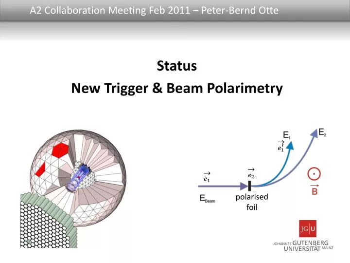
A2 Collaboration Meeting Feb 2011 – Peter-Bernd Otte Status New Trigger & Beam Polarimetry polarised foil
Brevity is the soul of wit FPGA = semiconductor chip • FPGA = • many electronics modules (like OR, MLU) • cables • no CPU! ~3 cm “VUPROM” from GSI with “Virtex 4” from XILINX ~ meters
Part A: New Experiment Trigger Setup of New Trigger CB level converter & cable cables masterVUPROM 1st stage VUPROM Exp. trigger 1st stage VUPROM Cellular Cluster Counter PID 1st stage VUPROM 70ns Computation time: 460ns for Multiplicity (LT = 98.7%) 20ns for Coplanarity (LT = 100%) 1st stage VUPROM
Part A: New Experiment Trigger cellular logic Steps • gather hit pattern (330ns) • Shrink clusters (60ns)(using set of rules)until no more changes • Count number of cells(20ns)= number of clusters • If desired cluster count trigger! Multiplicity cluster algorithm crystal scheme of CB
10 5 5 5 6 1 1 1 1 1 2 2 2 2 2 4 4 3 3 3 3 3 Part A: New Experiment Trigger Algorithm universality CB TAPS Shrink +120° & +240° rotated together 6x + 180° rotated together 6x cure wholes Not all rules are valid for all crystals at all times.
Part A: New Experiment Trigger Future New CB trigger • works • since several months in parallel to the existing one • awaitsintegration into L1/L2 • Remaining: • purity and efficiency? • More sophisticated triggers possible with: • CB, PID, TAPS, MWPC in combination for L1/L2
Part B: Beam polarimetry e- beam polarimetry • Good news: • No big energy shift anymore! • now correct calibration for “new Tagger” • only ~1ch due to optics e- Tagger radiator Measure degree of e- beam polarisation using Moeller polarimeter
Part B: Beam polarimetry e- beam polarimetry works, but: mark “C” long. degree of polarisation in %
Part B: Beam polarimetry 100 histograms/FPGA, here 2 samples Reason: detector. Proof: measured with two different electronics shaky measurements lowhumming Strong humming = time diff. /ch time diff. /ch
Part B: Beam polarimetry I5 and P7 channels of tagger: Humming = leads to biggest uncertainty in Moeller Humming in Tagger (no noise!)
Part B: Beam polarimetry Why not constant? e- source flux normalisation ~3% in pol. degree Taggersection A B C D E F G H I J K L M N O P
Part B: Beam polarimetry 8th Feb work on beam dump dump position changed (?) • 0.4% tagger magnet field change • 0 to 2 channels shift in Tagger • change in Moeller electronics and analysis needed Polarisation bit beam polarisation • possible to be obtained • MAMI energy dependent Beam polarimetry
Part B: Beam polarimetry 5 VUPROMs in Tagger rack = • Moeller electronics • planned as monitor for linear photons polarisation:indep. Tagger scalers with pair spectrometer as gate Patrik's talk • selection of single tagger channels for tests Electronics in Tagger area old
Part C: Problems Problem in existing exp. trigger Start of TDC at „CB Energy Sum“ 1% unclear 300ns Stop of TDC at „TCS Trig“ / Exp. Trigger
A2 Collaboration Meeting Feb 2011 – Peter-Bernd Otte Status elog
http://elog.office.a2.kph (user: a2online) elog from PSI (Stefan Ritt), open source, widely used und known • Many people in our group can assist • No text losses and locks anymore • Data from existing elog has been imported Data reliability • uses infrastructure from KPH computing group • virtual computer with RAID 5 (+ remote hot mirror) and snapshots paperless future Everybody or group can have his/their own logbook elog
Part C: Problems The all newkeyboard New keyboard for all German PhD students. Makes life easier… K.T. zu Guttenberg, Minister of Defence “Wrote” >20% of his PhD with Thanks for listening!
Part A: New Experiment Trigger Trigger = 2 hits in plane with incoming g (only azimuthal) |f1 – f2| = 180 deg divide CB into 48 azimuthal bins “hardwired” trigger with ANDs and ORs immediate trigger result Livetime = ~100% rate: 580Hz (while M1+ = 16k, M2+ = 3.6k) Coplanarity trigger 24x sublogic AND OR direction of beam Simulation by Cristina Collicott (D. Hornidge)
Part A: New Experiment Trigger Measured: Azimuth angle difference between hit channels in CB Coplanaritytrigger Number of clusters (M) determined by FPGA logic
Part A: New Experiment Trigger Setup of New Trigger: Multiplicity Trigger Detailed hit pattern needed full readout! signal to all: Send full hit pattern CB(NaI) level converter & cable cables masterVUPROM 1st stage VUPROM Exp. trigger 1st stage VUPROM PID 1st stage VUPROM 70ns 20ns 15ns 1st stage VUPROM + 100-120ns 310ns
Rates: livetime: 98.7% Next step: determine purity and efficiency Same trigger algorithms can be extended to cover also TAPS Multiplicity Trigger: Rates
Teil 2: Trigger-Logiken Im Vergleich
Part B: Moeller Polarimeter Use Moeller scattering • measure 2 coincident electrons DAQ necessary • Count asymmetry beam polarity Introduction electron beam polarimetry use Tagger polarised foil
Part B: Moeller Polarimeter Moeller radiator Tagger 4x VUPROMs Moeller Polarimeter Setup VUPROM 1 AB UV VUPROM 2 EF ST VUPROM 3 GH QR VUPROM 4 IJ OP Complete DAQ on a chip.Per FPGA:24x TDC (resolution 50ps) & 50 histograms 1 352 Detectors of Tagger
Part B: Moeller Polarimeter same e- energy and entry anglebutdifferent angles signs Simulate Moeller electrons (Tagger optics) energy shift in MeV Taggerchan. (450 MeV beam energy)
Part B: Moeller Polarimeter Sum of energy shift Simulate Moeller electrons (Tagger optics)