Download
1 / 48
480 likes | 603 Vues
This work explores the elastic quasimosaic effect in crystals, particularly focusing on quartz and silicon. Initially studied by Sumbaev in 1957, the quasimosaic effect involves broadening gamma-ray diffraction peaks due to the bending of atomic planes in anisotropic crystals. Results include predictions for different crystallographic orientations and the first experimental trials in 1999. Further advancements, including more recent measurements and calculations of the (111) plane, are discussed, paving the way for future experiments at CERN and IHEP.

E N D
Quasimosaic crystals Yu.M.Ivanov
Elastic quasimosaic (Sumbaev) effect • Studied by Sumbaev in 1957 • Resulted in broadening of gamma-ray diffraction peaks from bent quartz plates • Caused by bending of the reflecting atomic planes (initially flat and normal to large faces of plate) due to crystal anisotropy • Depends on choice of crystallographic plane and orientation angle of plate cutting relative to a normal to the chosen crystallographic plane Figure from article: O.I.Sumbaev, Reflection of gamma-rays from bent quartz plates, Sov. JETP 32(1957)1276
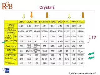
Quasimosaic effect in silicon • Calculations of deformed crystal plate done by V.M.Samsonov (Preprint No. 278, LIYaF AN SSSR, 1976). • Resulted in predictions of elastic quasimosaic effect for some other quartz and silicon plate orientations • Large elastic quasimosaicity for (011) plane of silicon predicted • Zero result in the first experiments in 1999 • New calculations using Samsonov approach and new measurements: - (111) plane, not (011) - published in JETP Letters 81, 99, 2005 Figure from article: V.M.Samsonov and E.G.Lapin, On some possibilities and pequliarities of a curved crystal use in crystal diffraction instruments, Preprint No. 587, LIYaF AN SSSR, 1980
Elastic quasimosaic in dependence on cut angle for Si (111) plane Plate bending radius R = 1 m Dq= 2k9 T , where T – thickness of plate k9 – deformation coefficient ( formula taken from V.M.Samsonov, E.G.Lapin, Preprint No. 587, LIYaF AN SSSR, 1980 )
Silicon cuts Oriented ingot Cut without quasimosaic φ Cut with quasimosaic
Quasimosaic effectin Si with X-rays Rocking curves for Si plate with quasimosaic before and after bending. Rocking curves for Si plate without quasimosaicbefore and after bending.
First quasimosaic silicon crystal prepared in 2002 for channeling experiment with 70 GeV protons
70 GeV p-beam Crystal 1 Magnets Collimator 5 m Crystal 2 S1 R=3 m 30 m Emulsion 1 Emulsion 2 S2 S3 Channeled_2 Channeled_1 35 m 4.6 m 1.3 m Background Layout of experiment at IHEP in April, 2002
Profile of 70 GeV proton beampassed through the crystal measured with emulsion: superposition of channeling and volume reflection effects
Explanation of the observed picture on emulsions Proton trajectories crossing the crystal and emulsions in horizontal plane (top view)
Crystals for experiment on extraction of high entensive proton beam at IHEP Plane (111) Length along beam 2.65 mm Bending angle 400 μrad
Result Beam in the U-70 ring 5.5∙1012p Intensity of extracted beam 4.0∙1012 p Efficiency 70%
Experiment on observation of volume reflection effect with 1 GeV protonsat PNPI, Gatchina Beam divergence ~ 160 μrad Beam size ~ 0.8 mm Critical angle for channeling ~ 170 μrad Crystal length along beam ~ 30 μm Bend angle of (111) planes ~ 380 μrad
One of unsuccessful attempts to bend a 30 μm crystal on 20 mm radius
Collimator Crystal mounted on goniometer
Horizontal profiles of the p-beam vs. crystal angle measured with PPC p-beam channeling Crystal angle, step 62.5 μrad reflection p-beam Channel number, step 200mm
Channeling experiment with 400 GeV protons CRYSTAL area FAR_DETECTOR area H8 beam line
QM2 Channeling angle (68.2 0.4) μrad Volume reflection deflection (12.7 0.6) μrad Volume capture ε (1.8 0.7) %
QM1 Channeling angle (77.0 0.4) μrad Volume reflection deflection (11.6 0.8) μrad Volume capture ε (2.6 0.8) %
QM2+QM1 Channeling angle Volume reflection deflection (23.4 0.7) μrad Volume capture ε (5 1) %
QM3 Channeling angle (72.7 0.8) μrad Volume reflection deflection (11.9 0.7) μrad Volume capture ε (5 1) %
QM4 Channeling angle (120.0 0.4) μrad Volume reflection deflection (12.7 0.5) μrad Volume capture ε (4.4 0.7) %
Design: sequence of quasimosaic crystals cut from a single initial plate p 1 Si plate 0.3 x 30 x 60 mm3 12 Si plates 0.3 x 8 x 14 mm3
Check with narrow X-ray beam Δθ N1 N2 ΔX N, counts ΔN=N2-N1 ΔN Δθ≈0.017x ΔN μrad ΔX Δθ < 40 μrad X, mm
Realization with evaporation technique Al-layer of 0.14 μm thickness Δθ = 0.14 μm / 12 mm = 12 μrad
Further steps • to improve prototype assemly for experimental run in May’07 at CERN • to prepare larger plates and assemble them for experiments at CERN and IHEP in the Fall’07