Download
1 / 10
100 likes | 126 Vues
Alternative Warman Slurry Pumps, Alternative Warman Slurry Pumps, warman pumps, warman slurry pumps, warman pump parts, warman pump wear parts, slurry pump parts, slurry pump spares. www.tobeepump.com

E N D
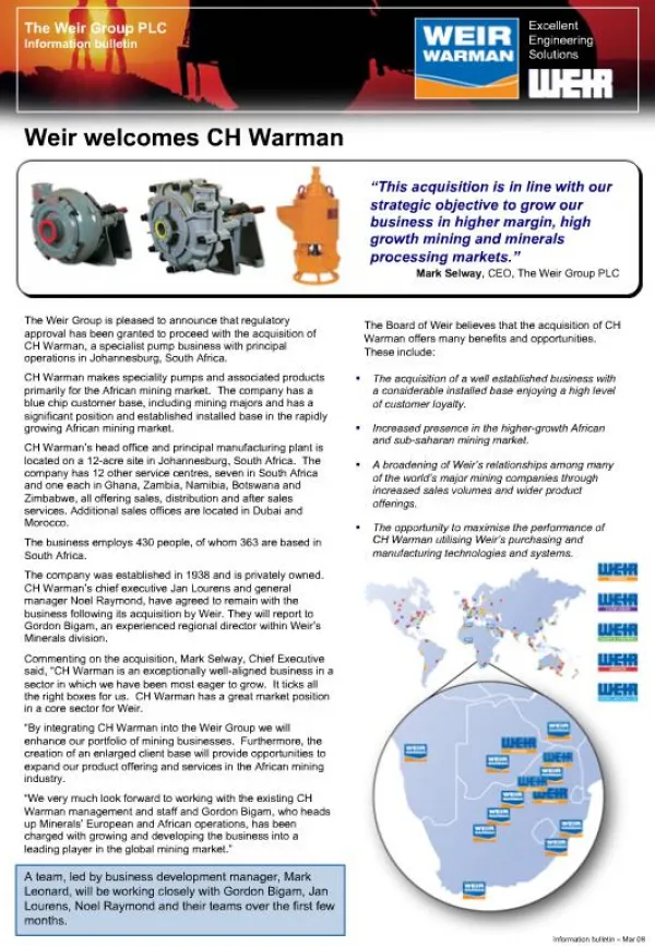
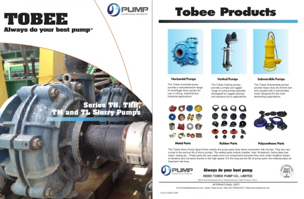
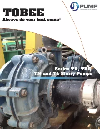
TOBEE Always do your best pump® Series TH, THH, TM and TL Slurry Pumps
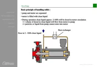
Tobee Series TH Pum Cartridge-type Shaft and Bearing Assembly A large diameter shaft with a short overhang minimizes deflection and vibration. Heavy-duty, grease-lubricated cylindrical and/or taper roller bearings are enclosed in a cartridge-type housing protected at both ends by a rotating labyrinth with double piston ring and patented -10 grease purged lip seal (see Figure 1 on page 6). Only four through bolts are required to hold the “cartridge” assembly in the frame. Pump Frame A rigid, one-piece casting cradles the “cartridge” shaft and bearing assembly. A minimal number of through bolts hold the pump casing to the frame. An easy means of external impeller adjustment is provided in a convenient position below the bearing housing. Slip-Fit Shaft Sleeve A reversible, 420 stainless steel shaft sleeve, through hardened to Rockwell 55C, with 0-rings at both ends, completely protects the shaft. Interchangeable Shaft Seal Tobee pumps provide complete interchangeability of seal arrangements. Full-flush, low-flow centrifugal, or mechanical seals can be fitted to any size pump. Centrifugal Shaft Seal Tobee’s centrifugal seal eliminates the need for a gland-water system and potential slurry contamination. More than 70% of all Tobee pumps are equipped with this seal arrangement. 2
mps: Design Features Impeller Front and rear shrouds have pump-out vanes. This design reduces recirculation and seal contamination. Hard metal and molded elastomer impellers are interchangeable. Cast-in impeller threads require no impeller insert or nuts. Outer Casing Casing halves of cast or ductile iron with external reinforcing ribs contain the wear liners and provide high operating pressure capabilities. EASE OF MAINTENANCE FEATURES: • Through-Bolt Design • Minimum Number of Casing Bolts • Zinc Chromate and Stainless Steel Nuts and Bolts Positively Attached Liner Hard metal liners are interchangeable with pressure molded elastomers. The elastomer liners are bolted, not bonded, to the outer casing. Elastomer seal rings back all liner joints. • Slip-Fit Shaft Sleeve • Cartridge-Type Shaft and Bearing Assembly • Cast-In Impeller Threads • Impeller-Release Collar on Large Models • Liners Positively Attached 3
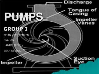
Tobee Typical Cr o s s - S e c t i o n Elastomer Lined, Gland Sealed VARIATIONS OF THE WARMAN CENTRIFUGAL SHAFT SEAL AVAILABLE WITH STANDARD OR OPTIONAL HS (HIGH-SEAL) CENTRIFUGAL SEALS COVER PLATE COVER PLATE LINER THROATBUSH COTTER FRAME PLATE FRAME PLATE LINER INSERT FRAME PLATE LINER INSERT STUD ‘O’ RING-SHAFT SPACER SHAFT SPACER LANTERN RESTRICTOR STUFFING BOX PACKING GLAND CLAMP BOLT LABYRINTH END COVER BEARING PLUG BEARING HOUSING BEARING-DRIVE END GREASE NIPPLE DRIVE END COVER SOCKET SET SCREW SHAFT SHAFT KEY METAL LINED ELASTOMER LINED LABYRINTH-DRIVE END The expeller ring is interchangeable with a gland sealed stuffing box. The expeller and expeller rings are made of 650 BHN high chrome iron as a standard but can be provided in other materials suitable for specific applications. RULE OF THUMB: If the suction pressure of the pump is no greater than 10% of the discharge pressure, the application is suitable for a centrifugal shaft seal. For variations from this general rule, consult your Warman Representative. PISTON RING END COVER SET SCREW END COVER GASKET ADJUSTING SCREW BASE UNIQUE WARMAN IMPELLER DESIGN GLAND GLAND BOLT SHAFT SLEEVE ‘O’ RING-SHAFT SLEEVE FRAME PLATE BOLT FRAME PLATE LINER STUD FRAME PLATE LINER Outward spiral of slurry in conventional pumps causes serious recirculation and consequent wear at the close impeller clearances. The pump-out vanes and concave impeller vane of a Warman pump force the slurry to form a double inward spiral. This results in uniform wear, a greater utilization of wearing parts, an increased shaft seal life, and sustained high efficiency. IMPELLER INTAKE JOINT RING COVER PLATE BOLT WARMAN DESIGN CONVENTIONAL DESIGN Figure 1 7 6 Standard -10 Bearing Seal (Retrofitable to older models) All impellers and liners are available in alloy or elastomer materials.
Wa rman Typical Cro s s - S e c t i o n Elastomer Lined, Gland Sealed VARIATIONS OF THE TOBEE CENTRIFUGAL SHAFT SEAL AVAILABLE WITH STANDARD OR OPTIONAL CENTRIFUGAL SEALS COVER PLATE COVER PLATE LINER THROATBUSH COTTER FRAME PLATE FRAME PLATE LINER INSERT FRAME PLATE LINER INSERT STUD ‘O’ RING-SHAFT SPACER SHAFT SPACER LANTERN RESTRICTOR STUFFING BOX PACKING GLAND CLAMP BOLT LABYRINTH END COVER BEARING PLUG BEARING HOUSING BEARING-DRIVE END GREASE NIPPLE DRIVE END COVER SOCKET SET SCREW SHAFT SHAFT KEY METAL LINED ELASTOMER LINED LABYRINTH-DRIVE END The expeller ring is interchangeable with a gland sealed stuffing box. The expeller and expeller rings are made of 650 BHN high chrome iron as a standard but can be provided in other materials suitable for specific applications. RULE OF THUMB: If the suction pressure of the pump is no greater than 10% of the discharge pressure, the application is suitable for a centrifugal shaft seal. For variations from this general rule, consult Tobee pump. PISTON RING END COVER SET SCREW END COVER GASKET ADJUSTING SCREW BASE UNIQUE TOBEE IMPELLER DESIGN GLAND GLAND BOLT SHAFT SLEEVE ‘O’ RING-SHAFT SLEEVE FRAME PLATE BOLT FRAME PLATE LINER STUD FRAME PLATE LINER Outward spiral of slurry in conventional pumps causes serious recirculation and consequent wear at the close impeller clearances. The pump-out vanes and concave impeller vane of a Tobee pump force the slurry to form a double inward spiral. This results in uniform wear, a greater utilization of wearing parts, an increased shaft seal life, and sustained high efficiency. IMPELLER INTAKE JOINT RING COVER PLATE BOLT TOBEE DESIGN CONVENTIONAL DESIGN Figure 1 7 6 Standard -10 Bearing Seal (Retrofitable to older models) All impellers and liners are available in alloy or elastomer materials.
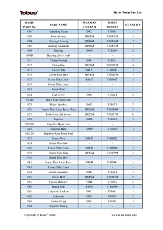
Tobee Pumps: Outline Dimensions Series “TH” Series “A” Type “L” PUMP SIZE A B C D U Key E F G H J K L M N WT/LBS METAL PUMP SIZE A B C D U Key E F G H J K L M N WT/LBS METAL mm Size mm Size R U B B E R R U B B E R 20 AL 18.15 11.26 8.27 5.75 20 6x6 2.24 6.06 5.67 3.39 5.04 1.22 – 3.54 .72 80 60 TH1.5/1 B 22.95 11.61 9.76 7.76 28 8x7 3.11 8.11 7.13 3.86 6.73 1.81 – 4.17 .74 195 170 50 BL 24.57 11.61 9.76 7.76 28 8x7 3.15 9.69 7.64 4.49 6.42 1.81 – 5.35 1.13 248 200 THH1.5/1C 29.88 15.98 12.24 10.00 42 12x8 4.76 10.59 10.63 7.64 10.00 – .43 4.76 2.61 700 – 75 CL 32.01 15.98 12.24 10.00 42 12x8 4.72 12.28 9.76 5.75 8.03 2.40 – 6.42 1.87 408 360 TH2/1.5B 23.31 11.61 9.76 7.76 28 8x7 3.11 8.54 7.99 4.49 7.24 1.31 – 4.49 .86 345 260 100 DL 37.40 19.37 14.33 12.99 65 18x11 6.42 13.94 12.13 7.52 10.28 3.27 – 7.36 2.07 784 754 TH3/2C 30.24 15.98 12.24 10.00 42 12x8 4.76 11.02 9.37 5.43 8.27 2.81 – 5.94 1.56 435 340 150 EL 47.95 24.49 17.64 17.99 80 22x14 8.74 18.74 15.87 9.76 12.76 5.24 – 9.33 .71 1630 1580 THH3/2D 38.82 19.37 14.33 12.99 65 18x11 6.46 15.28 15.12 10.00 14.49 – 2.00 7.99 3.28 1550 – 200 EM 52.64 24.49 17.64 17.99 80 22x14 8.74 22.99 24.13 15.00 18.50 – 3.27 12.52 1.97 3700 2650 THH3/2Q 40.16 21.26 18.11 11.81 60 18x11 5.91 15.31 15.12 10.00 14.40 – 3.19 7.99 2.22 1735 – 200 FM 60.67 33.74 25.00 24.02 100 28x16 11.02 22.52 24.13 15.00 18.50 2.76 – 12.52 1.54 4300 3250 TH4/3C 33.19 15.98 12.24 10.00 42 12x8 4.76 13.90 11.50 5.87 10.31 .93 – 7.36 2.11 550 520 250 EL 53.07 24.49 17.64 17.99 80 22x14 8.74 23.54 27.36 17.24 18.50 – 5.75 12.76 1.29 4100 3050 TH4/3D 37.13 19.37 14.33 12.99 65 18x11 6.46 13.90 11.50 5.87 10.31 3.94 – 7.36 2.04 700 640 250 FL 60.98 33.74 25.00 24.02 100 22x14 11.02 23.03 27.36 17.24 18.50 .31 – 12.76 .78 4400 3350 THH4/3E 48.82 24.49 17.64 17.99 80 22x14 8.74 19.37 19.37 12.99 17.00 – – 9.76 3.12 2750 – 300 RSL 57.48 36.22 23.23 17.72 85 22x14 8.46 25.83 29.13 18.70 22.44 – 7.28 11.81 3.62 5800 4500 THH4/3R 50.98 26.77 23.23 13.78 85 22x14 8.46 19.29 19.29 12.99 17.00 – 4.09 9.76 1.83 3090 – 300 SL 350 SL 67.72 69.92 36.22 30.71 17.72 120 36.22 30.71 17.72 120 32x18 11.02 25.39 29.13 18.70 22.44 32x18 11.02 27.36 32.48 20.87 24.41 – – 7.28 9.72 11.81 13.38 3.18 2.38 6300 7845 5000 6100 TH6/4D 40.20 19.37 14.33 12.99 65 18x11 6.46 16.69 15.98 9.02 13.31 .43 – 8.62 2.57 1475 1000 TH6/4E 46.38 24.49 17.64 17.99 80 22x14 8.74 17.05 15.98 9.02 13.31 5.43 – 8.62 2.96 1950 1400 400 STL 72.44 45.28 30.71 25.59 120 32x18 11.02 30.51 37.13 23.62 29.13 – 6.26 14.76 2.25 10225 7800 THH6/4F 61.26 33.74 24.96 24.02 100 28x16 10.98 23.03 24.25 16.26 21.50 1.00 – 12.01 2.96 5575 – 450 STL 73.82 45.28 30.71 25.59 120 32x18 11.02 32.28 40.75 25.98 31.50 – 8.74 15.75 1.94 12325 9275 THH6/4S 65.67 36.22 30.71 17.72 120 32x18 11.02 23.15 24.25 16.26 21.50 – 5.28 12.01 3.04 6335 – 500 STL 74.80 45.28 30.71 25.59 120 32x18 11.02 33.27 49.25 30.71 38.39 – 18.03 17.13 5.12 16000 12000 TH8/6E 51.26 24.49 17.64 17.99 80 22x14 8.74 21.93 21.69 12.52 18.11 – 2.44 11.50 3.23 3300 2165 500 TL 89.49 45.28 40.94 25.59 150 36x20 13.78 33.27 49.25 30.71 38.39 – 18.03 17.13 5.12 18000 14000 TH8/6F 59.33 33.74 25.00 24.02 100 28x16 10.98 21.22 21.69 12.52 18.11 3.54 – 11.50 2.56 4000 3065 550 TUL 94.49 57.48 41.34 35.43 150 36x20 13.78 40.55 51.69 33.86 38.39 – 9.53 19.69 3.17 24300 18200 THH8/6T 89.57 45.28 40.94 25.59 150 36x20 13.78 33.54 32.87 22.99 32.01 – 6.30 15.51 6.93 14490 – 650 TUL 98.74 57.48 41.34 35.43 150 36x20 13.78 44.33 61.14 40.16 46.25 – 18.11 22.83 5.12 41365 30650 TH10/8F 64.80 39.02 27.76 24.02 100 28x16 10.98 26.89 26.50 16.50 25.00 – .47 13.11 5.28 7040 5690 650 UL 1 2 1 . 1 0 56.69 54.13 35.43 240 56x32 18.50 45.87 61.14 40.16 46.25 – 18.11 22.83 6.66 47740 36825 TH10/8ST TH12/10F 68.82 67.76 45.28 30.71 25.59 120 39.02 27.76 24.02 100 32x18 11.02 27.24 26.50 16.50 25.00 1.06 28x16 10.98 29.65 29.76 18.27 26.50 – 13.11 15.00 5.63 4.25 8250 8290 6900 6190 – 4.09 Note: U dimensions and key sizes are in millimeters. All others are in inches. TH12/10ST 71.50 45.28 30.71 25.59 120 32x18 11.02 30.00 29.72 18.27 26.50 – 2.56 15.00 4.60 9500 7400 TH14/12F 69.76 39.02 27.76 24.02 100 28x16 10.98 31.61 36.89 24.76 32.76 – 10.35 15.98 4.13 12890 9090 TH14/12ST 73.74 45.28 30.71 25.59 120 32x18 11.02 31.97 36.89 24.76 32.76 – 8.82 15.98 4.48 14100 10300 TH16/14TU 91.34 57.48 41.34 35.43 150 36x20 13.78 37.52 41.26 25.98 35.00 – 3.31 17.76 6.56 22000 – TH20/18TU 97.44 57.48 41.34 35.43 150 36x20 13.78 43.31 55.67 37.01 48.43 – 16.42 22.83 2.77 38300 28100 Note: U dimensions and key sizes are in millimeters. All others are in inches. For installation, refer to certified drawings. 9 8
Wa rman Pumps: Outline Dimensions Series “A” Series “TL” PUMP SIZE A B C D U Key E F G H J K L M N WT/LBS METAL PUMP SIZE A B C D U Key E F G H J K L M N WT/LBS METAL mm Size mm Size R U B B E R R U B B E R TL20 A 18.15 11.26 8.27 5.75 20 6x6 2.24 6.06 5.67 3.39 5.04 1.22 – 3.54 .72 80 60 1.5/1 BAH 22.95 11.61 9.76 7.76 28 8x7 3.11 8.11 7.13 3.86 6.73 1.81 – 4.17 .74 195 170 TL50 B 24.57 11.61 9.76 7.76 28 8x7 3.15 9.69 7.64 4.49 6.42 1.81 – 5.35 1.13 248 200 1.5/1 CHH 29.88 15.98 12.24 10.00 42 12x8 4.76 10.59 10.63 7.64 10.00 – .43 4.76 2.61 700 – TL75 C 32.01 15.98 12.24 10.00 42 12x8 4.72 12.28 9.76 5.75 8.03 2.40 – 6.42 1.87 408 360 2/1.5 BAH 23.31 11.61 9.76 7.76 28 8x7 3.11 8.54 7.99 4.49 7.24 1.31 – 4.49 .86 345 260 TL100 D 37.40 19.37 14.33 12.99 65 18x11 6.42 13.94 12.13 7.52 10.28 3.27 – 7.36 2.07 784 754 3/2 CAH 30.24 15.98 12.24 10.00 42 12x8 4.76 11.02 9.37 5.43 8.27 2.81 – 5.94 1.56 435 340 TL150 E 47.95 24.49 17.64 17.99 80 22x14 8.74 18.74 15.87 9.76 12.76 5.24 – 9.33 .71 1630 1580 3/2 DHH 38.82 19.37 14.33 12.99 65 18x11 6.46 15.28 15.12 10.00 14.49 – 2.00 7.99 3.28 1550 – TM200 E 52.64 24.49 17.64 17.99 80 22x14 8.74 22.99 24.13 15.00 18.50 – 3.27 12.52 1.97 3700 2650 3/2 QHH 40.16 21.26 18.11 11.81 60 18x11 5.91 15.31 15.12 10.00 14.40 – 3.19 7.99 2.22 1735 – TM200 F 60.67 33.74 25.00 24.02 100 28x16 11.02 22.52 24.13 15.00 18.50 2.76 – 12.52 1.54 4300 3250 4/3 CAH 33.19 15.98 12.24 10.00 42 12x8 4.76 13.90 11.50 5.87 10.31 .93 – 7.36 2.11 550 520 TL250 E 53.07 24.49 17.64 17.99 80 22x14 8.74 23.54 27.36 17.24 18.50 – 5.75 12.76 1.29 4100 3050 4/3 DAH 37.13 19.37 14.33 12.99 65 18x11 6.46 13.90 11.50 5.87 10.31 3.94 – 7.36 2.04 700 640 TL250 F 60.98 33.74 25.00 24.02 100 22x14 11.02 23.03 27.36 17.24 18.50 .31 – 12.76 .78 4400 3350 4/3 EHH 48.82 24.49 17.64 17.99 80 22x14 8.74 19.37 19.37 12.99 17.00 – – 9.76 3.12 2750 – TL300 R 57.48 36.22 23.23 17.72 85 22x14 8.46 25.83 29.13 18.70 22.44 – 7.28 11.81 3.62 5800 4500 4/3 RHH 50.98 26.77 23.23 13.78 85 22x14 8.46 19.29 19.29 12.99 17.00 – 4.09 9.76 1.83 3090 – TL300 S TL350 S 67.72 69.92 36.22 30.71 17.72 120 36.22 30.71 17.72 120 32x18 11.02 25.39 29.13 18.70 22.44 32x18 11.02 27.36 32.48 20.87 24.41 – – 7.28 9.72 11.81 13.38 3.18 2.38 6300 7845 5000 6100 6/4 DAH 40.20 19.37 14.33 12.99 65 18x11 6.46 16.69 15.98 9.02 13.31 .43 – 8.62 2.57 1475 1000 6/4 EAH 46.38 24.49 17.64 17.99 80 22x14 8.74 17.05 15.98 9.02 13.31 5.43 – 8.62 2.96 1950 1400 TL400 ST 72.44 45.28 30.71 25.59 120 32x18 11.02 30.51 37.13 23.62 29.13 – 6.26 14.76 2.25 10225 7800 6/4 FHH 61.26 33.74 24.96 24.02 100 28x16 10.98 23.03 24.25 16.26 21.50 1.00 – 12.01 2.96 5575 – TL450 ST 73.82 45.28 30.71 25.59 120 32x18 11.02 32.28 40.75 25.98 31.50 – 8.74 15.75 1.94 12325 9275 6/4 SHH 65.67 36.22 30.71 17.72 120 32x18 11.02 23.15 24.25 16.26 21.50 – 5.28 12.01 3.04 6335 – TL500 ST 74.80 45.28 30.71 25.59 120 32x18 11.02 33.27 49.25 30.71 38.39 – 18.03 17.13 5.12 16000 12000 8/6 EAH 51.26 24.49 17.64 17.99 80 22x14 8.74 21.93 21.69 12.52 18.11 – 2.44 11.50 3.23 3300 2165 TL500 T 89.49 45.28 40.94 25.59 150 36x20 13.78 33.27 49.25 30.71 38.39 – 18.03 17.13 5.12 18000 14000 8/6 FAH 59.33 33.74 25.00 24.02 100 28x16 10.98 21.22 21.69 12.52 18.11 3.54 – 11.50 2.56 4000 3065 TL550 TU 94.49 57.48 41.34 35.43 150 36x20 13.78 40.55 51.69 33.86 38.39 – 9.53 19.69 3.17 24300 18200 8/6 THH 89.57 45.28 40.94 25.59 150 36x20 13.78 33.54 32.87 22.99 32.01 – 6.30 15.51 6.93 14490 – TL650 TU 98.74 57.48 41.34 35.43 150 36x20 13.78 44.33 61.14 40.16 46.25 – 18.11 22.83 5.12 41365 30650 10/8 FAH 64.80 39.02 27.76 24.02 100 28x16 10.98 26.89 26.50 16.50 25.00 – .47 13.11 5.28 7040 5690 TL650 U 1 2 1 . 1 0 56.69 54.13 35.43 240 56x32 18.50 45.87 61.14 40.16 46.25 – 18.11 22.83 6.66 47740 36825 10/8 STAH 12/10 FAH 68.82 67.76 45.28 30.71 25.59 120 39.02 27.76 24.02 100 32x18 11.02 27.24 26.50 16.50 25.00 1.06 28x16 10.98 29.65 29.76 18.27 26.50 – 13.11 15.00 5.63 4.25 8250 8290 6900 6190 – 4.09 Note: U dimensions and key sizes are in millimeters. All others are in inches. 12/10 STAH 71.50 45.28 30.71 25.59 120 32x18 11.02 30.00 29.72 18.27 26.50 – 2.56 15.00 4.60 9500 7400 14/12 FAH 69.76 39.02 27.76 24.02 100 28x16 10.98 31.61 36.89 24.76 32.76 – 10.35 15.98 4.13 12890 9090 14/12 STAH 73.74 45.28 30.71 25.59 120 32x18 11.02 31.97 36.89 24.76 32.76 – 8.82 15.98 4.48 14100 10300 16/14 TUAH 91.34 57.48 41.34 35.43 150 36x20 13.78 37.52 41.26 25.98 35.00 – 3.31 17.76 6.56 22000 – 20/18 TUAH 97.44 57.48 41.34 35.43 150 36x20 13.78 43.31 55.67 37.01 48.43 – 16.42 22.83 2.77 38300 28100 Note: U dimensions and key sizes are in millimeters. All others are in inches. For installation, refer to certified drawings. 9 8
Tobee Pumps: Selection Char t s Series “TH” Use this coverage chart as a first guide only. Series “A” Type “L” Use this coverage chart as a first guide only. The Series “A” Type “L” pumps are designed for continuous pumping of highly abrasive, medium-density slurries at medium heads. DRIVE ARRANGEMENTS Horizontal V-Belt Drive (CR or CL) The Series “TH” slurry pumps are designed for continuous pumping of highly abrasive, high-density slurries at maximum heads. DRIVE MODULE DESIGN Reverse Overhead Mounted Motor V-Belt Drive (ZV) Overhead Mounted Motor V-Belt Drive (CV) Direct Coupled Gear Reducer Drive (DC) 11 10
Wa rman Pumps: Selection Chart s Series “A” Use this coverage chart as a first guide only. Series “TL” Use this coverage chart as a first guide only. The Series “TL” pumps are designed for continuous pumping of highly abrasive, medium-density slurries at medium heads. DRIVE ARRANGEMENTS Horizontal V-Belt Drive (CR or CL) The Series “A” slurry pumps are designed for continuous pumping of highly abrasive, high-density slurries at maximum heads. Reverse Overhead Mounted Motor V-Belt Drive (ZV) Overhead Mounted Motor V-Belt Drive (CV) Direct Coupled Gear Reducer Drive (DC) 11 10
Tobee Products Horizontal Pumps Vertical Pumps Submersible Pumps The Tobee horizontal pump provide a comprehensive range of centrifugal slurry pumps for use in mining, chemical and industrial applications. The Tobee Vertical pumps provide a simpleyet rugged range of sumppumps specially developed forrugged cleanup and abrasiveslurry applications. The TobeeSubmersible pumps provide heavy duty all chrome wet end coupled with a submersible motor designed for the most demanding applications. Metal Parts Rubber Parts Polyurethane Parts Always do your best pump HEBEI TOBEE PUMP CO., LIMITED ADD:Hi-tech Development Zone | Shijiazhuang City | Hebei Province | China. INTERNATIONAL DEPT. Email:Sales@tobeepump.com | Skype:Tobee.pump | Mob:+86-18032034573 | Web:www.tobeepump.com © 2012 TOBEE PUMP