
Fiber Optics
E N D
Presentation Transcript
Introduction Optical fiber is a long thin transparent dielectric material which carries EM waves of visible and IR frequencies from one end to the other end of the fiber by means of TIR. NOTE: Glass or Plastic is used as Dielectric material. Optical fibers works as Wave guides in optical television signals, digital data to transmit voice television signals, digital data to any desired distance from one end to the other end of the fiber.
Optical fiber consists of three sections 1. Core 2. Cladding 3. Protective Jacket Core: It is an inner cylindrical material made up ofglass or plastic. Cladding: It is a cylindrical shell of glass or plastic material in which Core is inserted. Protective Jacket: The Cladding is enclosed in polyurethane jacket and it protects the fiber from surroundings. NOTE: The RI of core is slightly greater than the RI of Cladding. The normal standard values are 1.48 and 1.46 respectively.
Poly urethane protective jacket Cladding Core Structure of an Optical fiber • Principle:Optical fiber works on the principle of TIR. Once light ray enters into core ,it propagates by means of multiple TIR’ s at core-cladding interface.
NORMAL RERAR MEDIUM NORMAL r = 90 DENSAR MEDIUM
NORMAL RERAR MEDIUM DENSAR MEDIUM
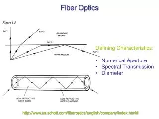
Acceptance Angle • The maximum angle of incidence at the end face of an Optical fiber for which the light ray can be propagated along Core-Cladding interface is known as maximum Acceptance angle. It is also called Acceptance cone half angle.
Core-Cladding interface B θr θ Core n1 θr θi A C Fiber axis Cladding n2 Incident light ray
Which is required expression for Maximum Acceptance Angle in optical fibers.
θm θm Acceptance Cone Acceptance Cone Rotating the Acceptance angle about the fiber axis describes the Acceptance Cone of the fiber. Light launched at the fiber end within this Acceptance Cone alone will be accepted and propagated to the other end of the fiber by total internal reflection.
Numerical Aperture • The light gathering capacity of an optical fiber is known as Numerical Aperture and it is proportional to Acceptance Angle. • It is numerically equal to sine of minimum Acceptance Angle. The ratio between the difference in RI’s of Core and Cladding to that of RI of core is called the fractional change.
TYPES OF OPTICAL FIBRES On the basis of variation of RI of core, the optical fibers are mainly classified into following types. i.e., 1.Step Index fiber 2.Gradex Index fiber NOTE: Based on Mode of propagation, the fibers are further divided into Single Mode and Multi Mode.
Single Mode Step Index fiber • The RI is constant for the core in this fiber. As we go radically from center of the core, the RI undergoes a step change at core-cladding interface . • The core diameter of this fiber is about 8 to 10µm and the outer diameter of cladding is 60 to 70µm. • There is only one path for light ray propagation. Hence it is called single mode step index fiber. • It is a reflective fiber since light is transmitted from one end to the other end of a fiber by TIR. • These are extensively used because distortion and transmission losses are very less.
60 to 70 µm 8 to 10 µm RI Radial distance Refractive index profile of single mode step index fiber
CORE RAY PROPAGATION CLADDING SINGLE MODE STEP INDEX FIBER
Multimode Step Index Fiber The construction of this fiber is similar to Single mode step index fiber but dimensions of Core and Cladding are much larger to have more number of paths for light propagation. The Core diameter varies from 50 to 200µm and the Cladding diameter varies from 100 to 250µm. It is also a reflective fiber since light is propagated in the form of multiple TIRS.
100 to 250 µm 50 to 200 µm RI Radial distance REFRACTIVE INDEX PROFILE OF MULTI MODE STEP INDEX FIBRE
GRADED INDEX FIBRE In this fiber , Radially the RI of Core continuously decreases from center to the surface. The RI is maximum at the center of Core and Minimum at the Surface. This fiber can be a single mode or Multimode ,the diameters of core and cladding varies from 50-200µm and 100-250µm respectively.
100 to 2500 µm 50 to 200 µm RI REFRACTIVE INDEX PROFILE OF SINGLE MODE GRADED INDEX FIBER Radialdistnce
100 to 250 µm 50 to 200 µm RI REFRACTIVE INDEX PROFILE OF MULTIMODE GRADED INDEX FIBRE Radialdistance
As RI changes continuously radially in Core, the light rays suffers continuous refraction with in the Core from its center to surface. • Thus the propagation of light rays are not due to TIR but by refraction. Therefore it is called Refractive fiber. • In this fiber, the light rays travel at different speeds in different parts. • Near the surface RI is least so, the light rays travel faster compared to the light rays near the axis. Because of this all the rays almost arrive at the same time at the other end of the fiber.
CLADDING CORE LIGHT PROPAGATION IN MUTI-MODE GRADED INDEX FIBRE
Optical fiber Communication System • An efficient optical fiber communication system requires high information carrying capacity such as voice signals, video signals over long distances with a minimum number of repeaters. It essentially consists of following parts. 1.Encoder 2. Transmitter 3.Wave guide 4.Receiver 5.Decoder
1.Encoder: It converts electric signal corresponding to analog information such as voice, figures, objects etc into a binary data. This binary data comes out in the form of stream of electrical pulses. • 2.TRANSMITTER: It mainly consists of drive circuit and a light source. Drive circuit supplies the electric pulses to the light source from the encoder. • NOTE: LED or diode laser is used as light source and it converts electrical signals are infected into optical signals. These optical signals are injected into wave guide.
TRANSMITTER OPTICAL SIGNAL Electrical signal DRIVE SOURCE LIGHT SOURCE ENCODER DECODER PHOTO DETECTOR SIGNAL RESTORER Wave guide AMPLIFIER receiver
Attenuation or Power loss in Optical fibers • The power of the light at the out put end is found to be always less than the power launched at the input end. • Attenuation is found t be a function of fiber material, wavelength of light and length of the fiber and it is measured in terms of the decibel. Attenuation mainly three types…. 1.Scattering losses 2.Absorption losses 3.Bending losses