LED 3
Tyler Blair. Preliminary Design Review. LED 3. 3D Graphical Display Ararat Adamian Brian McDonald Tyler Blair Adrian Williams. Tyler Blair. Outline of Presentation. Project objectives and purpose Approach Implementation Division of Labor Schedule Parts list Risks Critical Points.

LED 3
E N D
Presentation Transcript
Tyler Blair Preliminary Design Review LED3 3D Graphical Display Ararat Adamian Brian McDonald Tyler Blair Adrian Williams
Tyler Blair Outline of Presentation • Project objectives and purpose • Approach • Implementation • Division of Labor • Schedule • Parts list • Risks • Critical Points
Tyler Blair Project objectives and purpose Primary Objective: • Construct an 8x8x8 RGB LED cube with a programmable controller • Controller will come with a preset demo as well as the ability to receive custom programs from the user. • The LED cube will provide a 3D display for the programmable content and will function as a “3D Simulator”
Tyler Blair Extensions • The controller will interface with computer software such as matlab. This would allow the user to easily plot 3d functions on the cube. • The controller will have orientation modification capabilities on board. This would provide the user with the ability to zoom, shift or rotate the image. • The controller can wirelessly communicate with other wireless devices (smart-phones, computers, ect.)
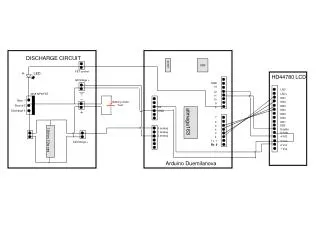
Ararat Adamian Outline of the Approach • Computer (or flash-drive or WiFi shield) provides micro-controller with data file • Micro-controller communicates with the shift-registers how and which LEDs to light • Shift registers output to the 8 LED strip.
Ararat Adamian Block Diagram Note: The shift registers will control each plane of 8*8 RGB LED’s. Only one plane will be on at a time, the illusion of all the planes being on will be from very rapidly switching planes.
Ararat Adamian Implementation • Micro-controller: • Atmega328 that will communicate with computer through USB • Line controller: • Array of 74HC595 shift registers with latch-able output • 8x8x8 LED cube: • 512 “540R2GBC-CC” RGB common cathode LEDs • LEDs will be mounted on thin plexiglass
Ararat Adamian Implementation Alternatives • Micro-controller: • Atmega1280 – More I/O pins and faster • Line controller: • Max7219 matrix controller in combination with AND gates • MSP430 micro-controller for each line of LEDs • 8x8x8 LED cube: • 512 Single Color LEDs • LEDs will be mounted in tubes
Adrian Williams Division of Labor • LED cube will be split into 8 planes of 64 LEDs (8x8), two group members will construct individual planes • One group member will design the PCB for the micro-controller and Line-controller circuits. • One group member will work on firmware to interface between computer and shift registers
Adrian Williams Preliminary Schedule
Adrian Williams Schedule
Brian McDonald Preliminary Parts List 512 RGB LEDs 5 mm 24 8-bit Shift registers (74HC595) 8 High Current(5A) NPN transistors 1 Micro-controller (Atmega328p) 1 USB to serial (FTDI FT232RL) 12 1/8 plexiglass planes 1 5V, 1A regulator 1 5V, 5A regulator Various capacitors, resistors, crystals, etc.
Brian McDonald Cost
Brian McDonald Risks • Project is heavily hardware orientated • Time constraints • Feasibility of extensions • Unfamiliarity with WiFi technology • Power requirements • Heat dissipation • LEDs are too bright or not bright enough
Brian McDonald Critical points • CDR -All Parts received, PCB designed and ordered, 8x8 RBG plane constructed and tested with simple graphics, Cube is being built and Micro-controller being programmed for 3D implementation • Milestone 1 -Cube is fully assembled, Micro-controller is programmed and ready to receive input from software/wireless/USB device, Power Supply is nearly finished, Cube is being tested • Milestone 2 -All Hardware is completely built and tested, Software is being designed to interface with cube, USB/Wireless interfaces are being built, Documentation is being completed • Expo - awesome