Registers
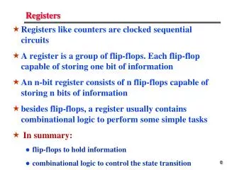
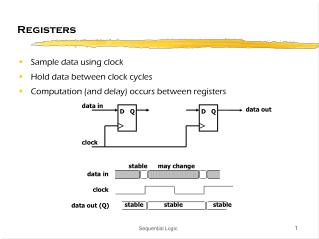
Registers. The filp-flops are essential component in clocked sequential circuits. Circuits that include filp-flops are usually classified by the function they perform. Two such circuits are registers and counters.

Registers
E N D
Presentation Transcript
Registers • The filp-flops are essential component in clocked sequential circuits. • Circuits that include filp-flops are usually classified by the function they perform. Two such circuits are registers and counters. • An n-bit register consists of a group of n flip-flops capable of storing n bits of binary information.
Registers • In its broadest definition, a register consists a group of flip-flops and gates that effect their transition. • The flip-flops hold the binary information. • The gates determine how the information is transferred into the register. • Counters are a special type of register. • A counter goes through a predetermined sequence of states.
Register with Parallel Load • A clock edge applied to the C inputs of the register of Fig. 6-1 will load all four inputs in parallel. • For synchronism, it is advisable to control the operation of the register with the D inputs rather than controlling the clock in the C inputs of the flip-flops. • A 4-bit register with a load control input that is directed through gates and into the D inputs of the flip-flops si shown in Fig. 6-2.
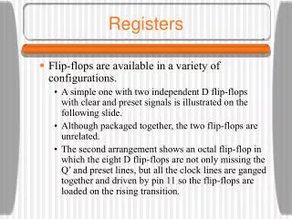
Registers • Fig 6-1 shows a register constructed with four D-type filpflops. • “Clock” triggers all flip-folps on the positive edge of each pulse. • “Clear” is useful for clearing the register to all 0’s prior to its clocked operation.
Register with Parallel Load • When the load input is 1 , the data in the four inputs are transferred into the register with next positive edge of the clock. • When the load input is 0 ,the outputs of the flip-flops are connected to their respective inputs. • The feedback connection from output to input is necessary because the D flip-flops does not have a “no change” condition.
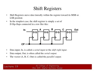
Shift Registers • A register capable of shifting its binary information in one or both direction is called a shift register. • All flip-flops receive common clock pulses, which activate the shift from one stage to the next. • The simplest possible shift register is one that uses only flip-flops
Shift Register Applications • Shift Registers are an important Flip-Flop configuration with a wide range of applications, including: • Computer and Data Communications • Serial and Parallel Communications • Multi-bit number storage • Sequencing • Basic arithmetic such as scaling (a serial shift to the left or right will change the value of a binary number a power of 2) • Logical operations
SISO Flip-Flop Shift Register • a Serial In Serial Out shift register has a single input and a single output D Q Q D Q Q Output D Q Q Input
SIPO Flip-Flop Shift Register • a Serial In Parallel Out shift register has a single input and access to all outputs Output Output Output D Q Q D Q Q D Q Q Input
PISO Flip-Flop Shift Register • a Parallel In Serial Out shift register requires additional gates, and the parallel input must revert to logic low. Input Input Input Output D Q Q D Q Q D Q Q
PIPO Flip-Flop Shift Register • a Parallel In Parallel Out register has the simplest configuration. It represents a memory device. Input Input Input D Q Q D Q Q D Q Q Output Output Output
Universal Shift Register • A clear control to clear the register to 0. • A clock input to synchronize the operations. • A shift-right control to enable the shift operation and the serial input and outputlines associated with the shift right. • A shift-left control to enable the shift operation and the serial input and outputlines associated with the shift left.
Universal Shift Register • A parallel-load control to enable a parallel transfer and the n input lines associated with the parallel transfer. • n parallel output lines. • A control state that leaves the information in the register unchanged in the presence of the clock. • If the register has both shifts and parallel load capabilities, it is referred to as a universal shift register.
Universal Shift Register Table 6-3 Function Table for the Register of Fig. 6-7
Universal Shift Register • Shift registers are often used to interface digital system situated remotely from each other. • If the distance is far, it will be expensive to use n lines to transmit the n bits in parallel. • Transmitter performs a parallel-to-serial conversion of data and the receiver does a serial-to-parallel conversion.